Moving bed heat exchanger for circulating fluidized bed boiler
What is Al technical title?
Al technical title is built by PatSnap Al team. It summarizes the technical point description of the patent document.
a technology of fluidized bed and heat exchanger, which is applied in the direction of fluidised bed combustion apparatus, combustion types, lighting and heating apparatus, etc., can solve the problem that the heat absorption of furnace enclosure walls and in-furnace panels is not sufficient to achieve the desired operating temperature
Active Publication Date: 2015-10-20
GENERAL ELECTRIC TECH GMBH
View PDF36 Cites 0 Cited by
Summary
Abstract
Description
Claims
Application Information
AI Technical Summary
This helps you quickly interpret patents by identifying the three key elements:
Problems solved by technology
Method used
Benefits of technology
[0012]Accordingly, it is an objective of the present invention to provide an improved technique for recycling the ash that is produced from the combustion of fossil fuels, such as, for example, the recycling of the ash that is produced from the combustion of fossil fuels in a circulating fluidized bed boiler.
[0013]It is another object of the present invention to provide an improved technique for removing heat during the recycling of the ash that is produced from the combustion of fossil fuels.
Problems solved by technology
While most of the heat absorption is through the furnace walls and the in-furnace panels, on larger circulating fluidized bed boilers, heat absorption by the furnace enclosure walls and in-furnace panels is insufficient to achieve the desired operating temperatures.
Method used
Image
Click on the blue label to locate the original text in one second.
Reading with bidirectional positioning of images and text.
Examples
Embodiment Construction
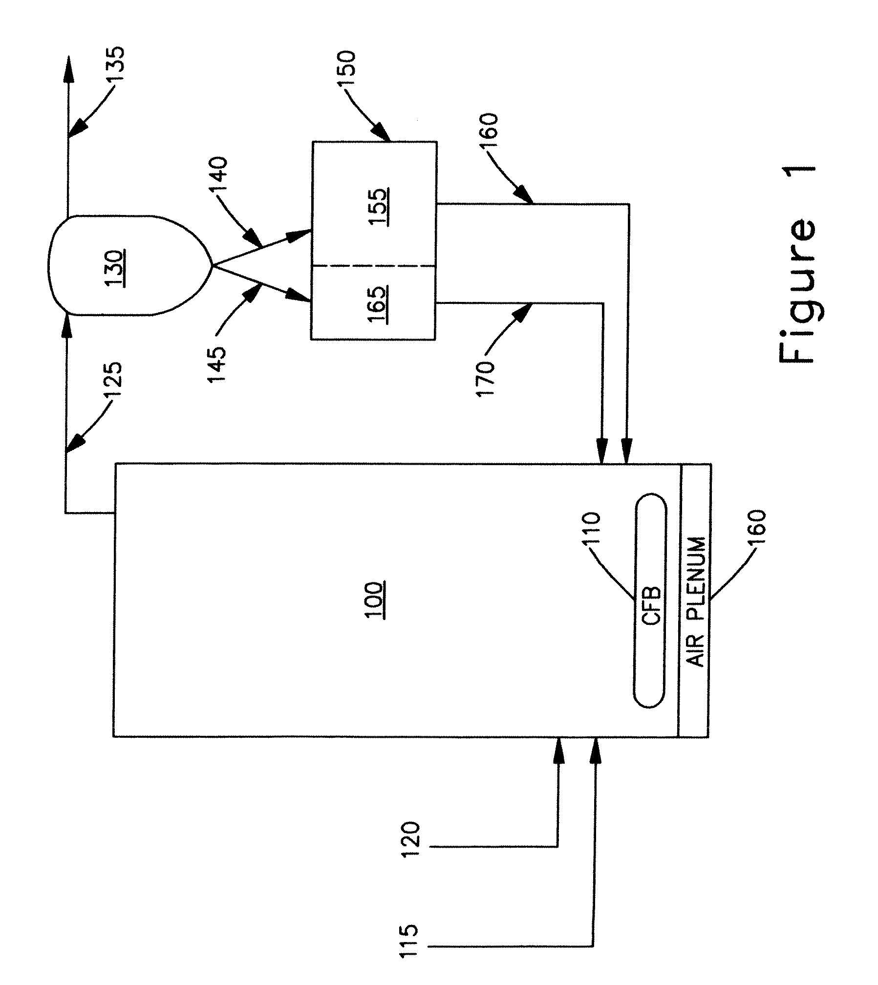
[0031]In FIG. 1 of the drawings there is illustrated a circulating fluidized bed boiler 100 embodying a circulating fluidized bed 110. As best understood with reference to FIG. 1, fresh fuel, typically crushed coal, is fed to the circulating fluidized bed 110 via a conveying line 115, and fresh sorbent, commonly crushed limestone, is fed also to the circulating fluidized bed 110 via a conveying line 120.
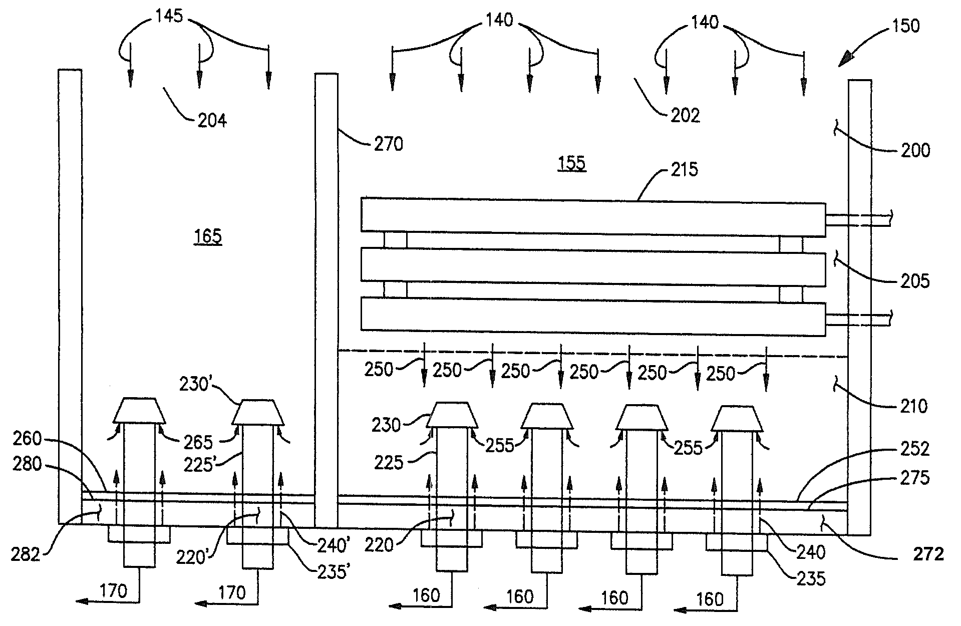
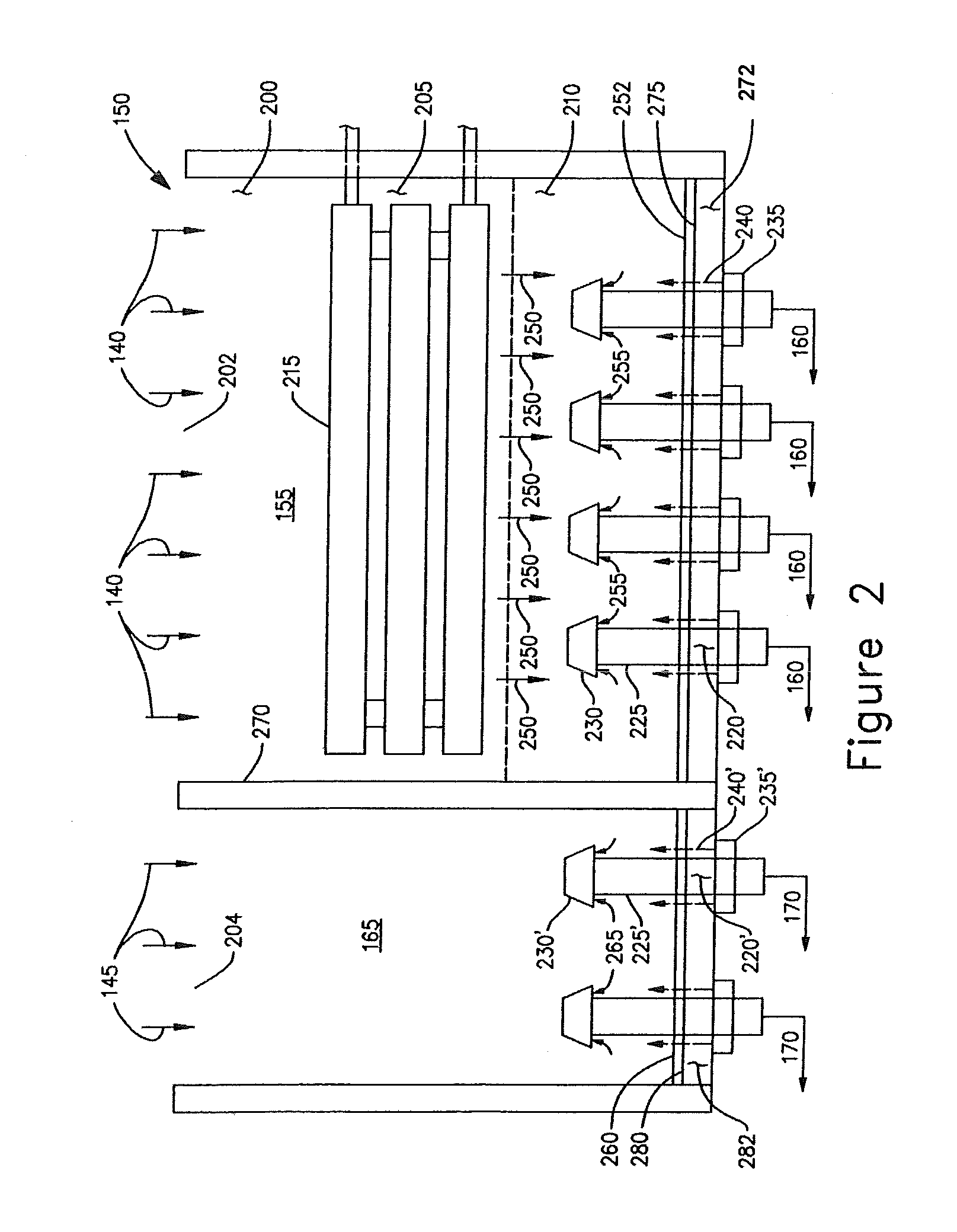
[0032]In addition, with further reference to FIG. 1 recycled hot ash is also transported from a seal pot 165 to the circulating fluidized bed 110 via a conveying line 170. Additionally, recycled cool ash is also transported from a moving bed heat exchanger (MBHE) 155 to the furnace, i.e., reaction chamber, of the circulating fluidized bed boiler 100 via a conveying line 160.
[0033]Continuing a plenum 160, as illustrated in FIG. 1, supplies air to the fresh fuel, fresh sorbent and recycled ash particles that are fed to the furnace of the circulating fluidized bed boiler 100 in order to...
PUM
Abstract
A moving bed heat exchanger (155) includes a vessel having an upper portion (200), a lower portion (210) with a floor (272) including a discharge opening therein, and an intermediate portion (205). The vessel directs a gravity flow of hot ash particles (140) received thereby from the upper portion (200) through the intermediate portion (205) to the floor (272) of the lower portion (210) of the vessel, where the hot ash particles (140) are collected. Tubes in the intermediate portion (205) of the vessel direct a flow of working fluid in a direction substantially orthogonal to the direction of the gravity flow of the hot ash particles (140) through the intermediate portion (205) of the vessel such that heat from the hot ash particles (140) is transferred to the working fluid thereby cooling the hot ash particles (140).
Description
RELATED APPLICATION[0001]The present application is related to U.S. application Ser. No. 09 / 740,356, filed Dec. 18, 2000 and entitled “Recuperative and Conductive Heat Transfer System” (now U.S. Pat. No. 6,554,061, issued on Apr. 29, 2003), U.S. application Ser. No. 10 / 451,830, filed Oct. 29, 2002 and entitled “Circulating Fluidized Bed Reactor Device” (now U.S. Pat. No. 6,779,492, issued on Aug. 24, 2004), and U.S. application Ser. No. 10 / 451,769, filed Oct. 29, 2002 and entitled “Centrifugal Separator in Particular for Fluidized Bed Reactor Device” (now U.S. Pat. No. 6,938,780, issued on Sep. 6, 2005), the disclosures of which are incorporated herein in their entirety by reference.FIELD OF THE INVENTION[0002]The present invention relates generally to fluidized bed type fossil fuel fired heat generating systems, and more particularly to the re-circulating of heated solids in a fluidized bed type fossil fuel fired heat generating system.BACKGROUND OF THE INVENTION[0003]Heat generati...
Claims
Application Information
Patent Timeline
Application Date:The date an application was filed.
Publication Date:The date a patent or application was officially published.
First Publication Date:The earliest publication date of a patent with the same application number.
Issue Date:Publication date of the patent grant document.
PCT Entry Date:The Entry date of PCT National Phase.
Estimated Expiry Date:The statutory expiry date of a patent right according to the Patent Law, and it is the longest term of protection that the patent right can achieve without the termination of the patent right due to other reasons(Term extension factor has been taken into account ).
Invalid Date:Actual expiry date is based on effective date or publication date of legal transaction data of invalid patent.