Drying device and image forming apparatus

a drying device and image technology, applied in drying machines, lighting and heating apparatus, drying machines, etc., can solve the problem of uneven drying air blowing rate across the width direction of recording medium, and achieve the effect of reducing airflow rate and increasing energy efficiency of fan(s)

Inactive Publication Date: 2015-10-20
FUJIFILM CORP
View PDF18 Cites 3 Cited by
  • Summary
  • Abstract
  • Description
  • Claims
  • Application Information

AI Technical Summary

Benefits of technology

[0011]In consideration of the above circumstances, an object of the present invention is to provide a drying device and an image forming apparatus that can blow drying air onto a recording medium at a uniform rate across the width direction of the recording medium, whilst suppressing an increase in the moisture content of the drying air.
[0017]Further, an increase in the moisture content of the drying air can be suppressed due to using external air for the drying air.
[0019]According to the above configuration, the energy efficiency of the heating and blowing section is improved since the drying air, which is blown out from the heating and blowing section, can be taken back into the airflow path through the circulation opening as recirculated air and recirculated.
[0037]According to the above configuration, providing the constricted opening increases the airflow rate of drying air and raises the water vapor removal efficiency.
[0047]According to the above configuration, the controller controls for example to decrease the airflow rate when the jetted liquid droplet amount is less than a given standard value, and to increase the airflow rate when the jetted liquid droplet amount is more than a given standard value. The recording medium can accordingly be dried reliably, and the energy efficiency of the fan(s) can also be raised.

Problems solved by technology

However, in the configuration of JP-A No. 2011-224932, the rate at which drying air is blown onto the recording medium is not uniform across the width direction of the recording medium since the drying air is blown from the side of the recording medium.

Method used


Image

  • Drying device and image forming apparatus
  • Drying device and image forming apparatus
  • Drying device and image forming apparatus

Examples


modified examples

[0178]Detailed explanation has been given regarding a particular exemplary embodiment of the present invention, however the present invention is not limited to this exemplary embodiment and it would be clear to a practitioner skilled in the art that various exemplary embodiments are possible within the scope of the present invention. Appropriate combinations from the plural exemplary embodiments described above may also be implemented. Appropriate combinations with the following modified examples may also be implemented.

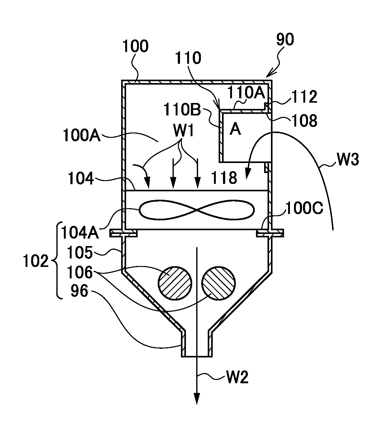
[0179]For example, explanation has been given regarding a case wherein the airflow path 100A extends in a direction orthogonal to the first horizontal conveyance path 70A, however it is sufficient for the airflow path 100A to intersect with the conveyance path.

[0180]As illustrated in FIG. 9A, a configuration may be adopted wherein fresh air W1 is introduced into the airflow path 100A with an external air intake fan 94A only provided at one side of the airflow path 10...


PUM


Abstract

There is provided a drying device including: an airflow path extending in a direction intersecting with a conveyance path of a recording medium; an external air intake section that introduces external air into the airflow path; and a heating and blowing section provided to the airflow path that heats external air introduced into the airflow path and blows drying air onto a front face of the recording medium being conveyed on the conveyance path.

Description

CROSS-REFERENCE TO RELATED APPLICATION[0001]This application is based on and claims priority under 35 USC 119 from Japanese Patent Application No. 2012-019251 filed on Jan. 31, 2012, the disclosure of which is incorporated by reference herein.BACKGROUND[0002]1. Technical Field[0003]The present invention relates to a drying device and to an image forming apparatus.[0004]2. Related Art[0005]In image forming apparatuses, a known liquid droplet jetting recording type image forming apparatus includes liquid droplet jetting heads with multiple nozzles arranged in a row. Paper (a recording medium) is conveyed with respect to the liquid droplet jetting heads to form an image (including text) on the paper by jetting liquid droplets of for example ink from the nozzles towards the paper.[0006]Processing performed after image forming in such liquid droplet jetting recording type image forming apparatuses reduces paper distortion (curling and cockling) caused by moisture in the liquid droplets b...

Claims


Application Information

Patent Timeline
Patent Type & Authority Patents(United States)
IPC IPC(8): F26B17/28B41J11/00F26B21/00B41F23/04
CPCF26B21/004B41F23/0443B41F23/0466B41J11/002B41J11/0015B41J11/00222
Inventor CHIWATA, YUHEIOHBA, MASAHIROHASEGAWA, MASATAKA
Owner FUJIFILM CORP
Why Eureka
Try Eureka