Composite structural member

a composite structural and composite technology, applied in the direction of domestic objects, air transportation, vehicle components, etc., can solve the problems of poor compliance with the skin under bending, poor axial stiffness, and high rigidity of bonded joints, so as to achieve low axial stiffness, high rigidity, and low rigidity.

Inactive Publication Date: 2015-10-27
AIRBUS OPERATIONS LTD
View PDF14 Cites 2 Cited by
  • Summary
  • Abstract
  • Description
  • Claims
  • Application Information

AI Technical Summary

Benefits of technology

[0011]The invention is advantageous in that a portion of a ply, or group of plies, is substituted for a ply portion having a different fibre characteristic. The ply containing the substitution may be provided between continuous plies in the stack. The fibre characteristic may be its modulus, orientation, and / or material. For example, a ply having an orientation of 0 degrees may have a substituted portion containing fibres of + / −45 degrees so as to beneficially reduce axial stiffness in the substituted region of the structural member. Alternatively, the substituted ply portion could have fibres of lower modulus but the same orientation as those of the remainder of the ply to achieve the same effect of lowing the axial stiffness in the substituted region. The first and second ply portions may have fibres of the same material (e.g. carbon Intermediate Modulus (IMS) for one portion and carbon High Tensile Strength (HTS) for the other), or the ply portions may have fibres of different materials (e.g. carbon and glass) so as to achieve the reduction in axial stiffness in the substituted region.
[0013]Adjacent edges of the first and second portions may be abutting to help ensure there are no local thickness variations. However, efficient load transfer within the laminate may be achieved by overlapping adjacent edges of the first and second portions. The overlapping distance can be controlled to minimise the impact on local thickness changes if required to achieve simplified tooling requirements.
[0017]The second portion extends up to an edge of the structural member and the first portion is disposed inboard of the edge. Where the structural member is a stringer, the ply substitution may be in the run out region. In one embodiment, one or more plies having fibres oriented substantially in the stringer longitudinal direction have a portion in the run out region substituted with fibres having a different characteristic such that the stringer has a lower axial stiffness at the run out region compared with the remainder of the stringer. Where the structural member is a panel having a man-hole cut out, for example, the ply substitution may be in the region adjacent the cut out. In one embodiment, the panel desirably has high stiffness inboard of the cut out, and lower stiffness, and hence improved damage tolerance, in the region adjacent the cut out.

Problems solved by technology

As a result, geometric tapering and hence load transfer in the stringer termination region, tends to be relatively abrupt with poor compliance with the skin under bending.
These bonded joints also tend to be susceptible to peeling failures.
These factors contribute to cause premature cracking, peeling and disbond growth in these regions.
As a result of this earlier termination, the skin thickness must be increased following the stringer run-out giving rise to a weight penalty.
Furthermore, additional supporting structural members may require modification to account for new loads, and repair of the run-out region becomes more complicated.
Further geometric modifications in the stringer termination region are possible but these have associated tooling, tolerance and manufacturing complexities.

Method used


Image

  • Composite structural member
  • Composite structural member
  • Composite structural member

Examples


Embodiment Construction

)

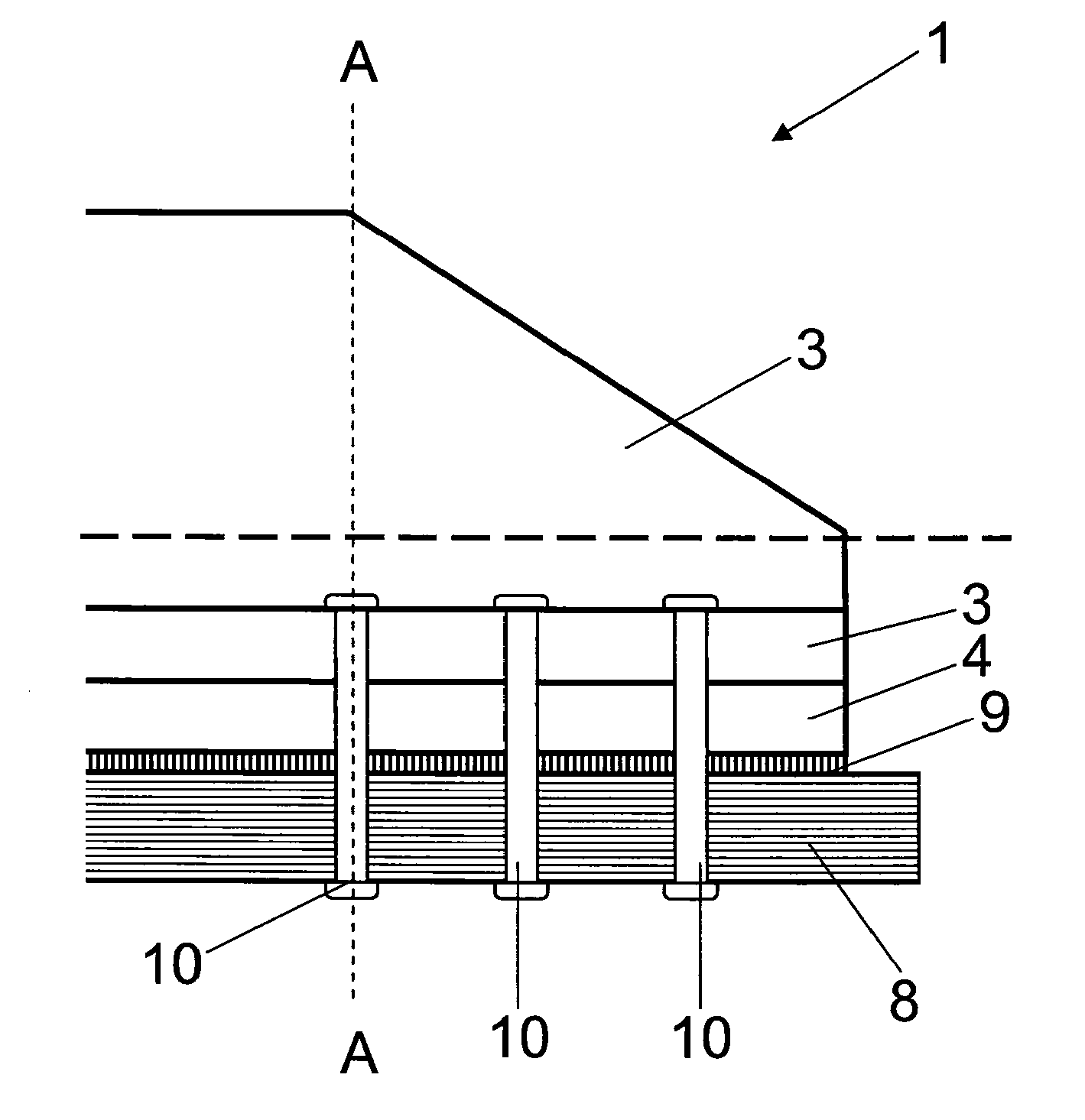
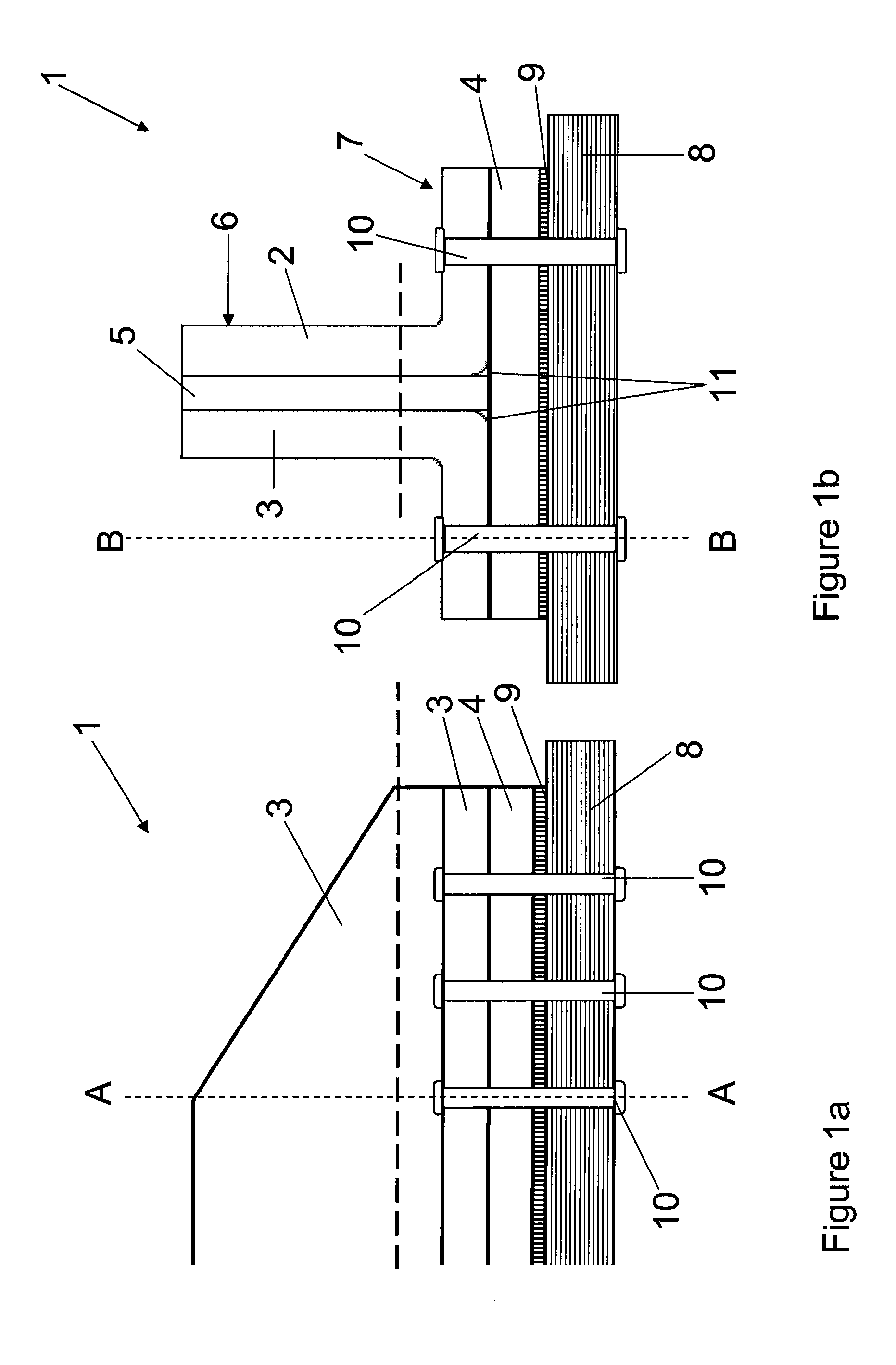
[0033]FIGS. 1a and 1b illustrate a “T” section composite stringer 1 comprising a pair of “L” section members 2, 3, a base stack 4 and a central stack 5. FIG. 1b illustrates the cross section view along A-A in FIG. 1a, and FIG. 1a illustrates the cross section view along B-B in FIG. 1b.

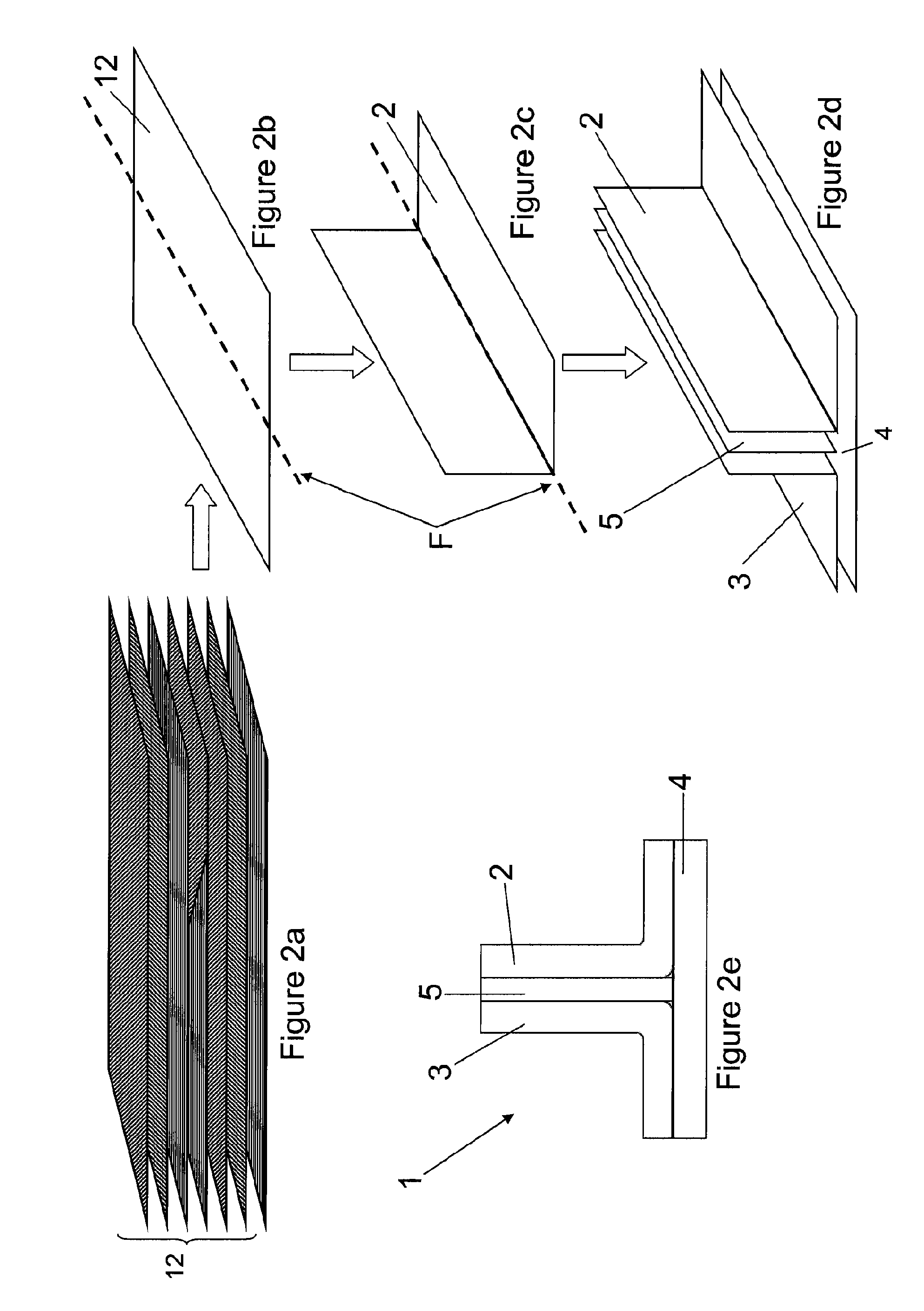
[0034]The stringer 1 is attached to a laminate composite panel 8 by a bonding line 9 and an array of fasteners 10 of conventional type. The bond line 9 and the fasteners 10 help to transfer load at the stringer termination into the panel 8. Each of the stringer components 2, 3, 4 and 5, comprise a laminate stack of composite structural plies, as will be described in greater detail below. Due to the limited bend radius of the “L” section components 2, and 3, noodles 11 are provided in the cleft between the back-to-back “L” sections 2, 3 and the central stack 5, as best seen in FIG. 1b. The noodles 11 comprise fibre filler material.

[0035]Although the stringer 1 shown in FIGS. 1a and 1b includes a base ...


PUM

PropertyMeasurementUnit
thicknessaaaaaaaaaa
thicknessaaaaaaaaaa
thickaaaaaaaaaa

Abstract

A method of manufacturing a composite structural member (1), comprising the step of laying up a stack of fiber reinforced laminate plies (12), wherein at least one of the plies is laid up as discrete first (13) and second ply (14) portions, and the fibers of the second portion (14) have a different characteristic from those of the first portion (13). Also, a composite structural member (1) manufactured according to the method.

Description

[0001]This application is the U.S. national phase of International Application No. PCT / GB2011 / 050620, filed 28 Mar. 2011, which designated the U.S. and claims priority to GB Application No. 1005308.0, filed 30 Mar. 2010, the entire contents of each of which are hereby incorporated by reference.FIELD OF THE INVENTION[0002]The present invention relates to a method of manufacturing a composite structural member, and to a composite structural member so formed.BACKGROUND OF THE INVENTION[0003]In many structures, panels have attached reinforcing structural members to improve buckling stability. In aircraft, a skin panel (e.g. a wing cover) may have reinforcing structural members (e.g. stringers). The reinforcing structural members meet with various obstructions and so need to be “run-out”, or terminated. The problem of transferring load between the reinforcing member and the skin panel that it is reinforcing in the run-out region is well known. A bond line is typically used to attach the ...

Claims


Application Information

Patent Timeline
Patent Type & Authority Patents(United States)
IPC IPC(8): B29C70/22B64C3/26B64C3/18B29D99/00B64C1/06B64C1/12B29L31/30
CPCB29C70/22B29D99/0014B64C1/064B64C1/12B64C3/182B64C3/26B29L2031/3085Y02T50/433Y10T428/24182Y02T50/40B64U20/65B32B5/12B32B5/26B32B2605/18
Inventor ELI-ELI, MATTHEWBRIAN, DAVIDCOSENTINO, ENZOLLOYD, JAMESALMEIDA, FILIPEBURLEIGH, CHRISTOPHER DAVID
Owner AIRBUS OPERATIONS LTD
Why Eureka
Try Eureka