Control system and method for detecting the rotational speed of an internal combustion engine

a control system and internal combustion engine technology, applied in hardware monitoring, structural/machine measurement, registering/indicating, etc., can solve the problems of insufficient traditional calculation and least one tooth gap, and achieve the effect of preventing meshing, improving accuracy, and small rotational speed differen

Inactive Publication Date: 2015-10-27
SEG AUTOMOTIVE GERMANY GMBH
View PDF17 Cites 2 Cited by
  • Summary
  • Abstract
  • Description
  • Claims
  • Application Information

AI Technical Summary

Benefits of technology

[0008]One aspect of the present invention is to reduce a sector section of the signal wheel to be scanned, in particular to evaluate a sector section of approximately 6° to 35° to increase the accuracy of a determination of the rotational speed of the internal combustion engine.
[0012]To increase the accuracy of determining the rotational speed, an additional piece of information in the form of a time stamp is added to each detected mark. Thus, an absolute time is assigned to each detected mark instead of assigning a relative time. The rotational speed curve may thus be mapped highly accurately.
[0016]According to a method which refines the present invention, a check is made in one condition as to whether there has been a reversal in the direction of rotation. If this is the case, the rotational speed is set to “0” and then a calculated rotational speed n is calculated again and output when a second mark having the same direction of rotation is detected. This has the advantage of mapping the rotational speed curve accurately up to the actual standstill and to mesh with a preferably small rotational speed difference. This prevents meshing with negative rotational speeds which are too low.
[0017]According to an alternative or additional further preferred method, the accuracy for calculating the rotational speed is increased by increasing the computation cycle. A traditional computation cycle for the rotational speed and angle calculation by the engine control unit has a computation interval of 10 milliseconds, for example. The computation cycle is preferably further shortened to 5 milliseconds, in particular preferably to 1 millisecond and particularly advantageously to less than 1 millisecond. Alternatively or additionally, the rotational speed may be calculated, controlled in relation to a signal event, in particular synchronously with the mark. The detected signal may thus be made available together with a calculated rotational speed, preferably in real time.
[0018]This object is also achieved by a computer program, which may be loaded into a program memory having program instructions as the microcomputer to execute all steps of a method described above or below, in particular when the computer program product is executed in the control system. The computer program product is preferably stored on a nonvolatile memory in the form of a microchip. The computer program product may preferably be implemented as a module in an existing control system. The computer program product has the additional advantage that it is easily adaptable to empirical values and thus a maintenance or optimization of individual method steps may be implemented inexpensively with little effort.
[0019]The object is also achieved by a control system having a detection device, an evaluation device, which includes a microcomputer having a program memory for accurate detection of the rotational speed of an internal combustion engine, and by the fact that the method described above may be implemented using the control system. There are a variety of possible applications of such a control system, which may be an engine control unit, for example. It may be advantageous, for example, to provide a high-precision rotational speed detection for an accurately timed point for injection of fuel into the cylinders of an internal combustion engine or to accordingly activate valves of the internal combustion engine with high accuracy. Another preferred application presents itself for predicting the rotational speed curve of a coasting internal combustion engine when using a start-stop system of a motor vehicle to mesh with the annular gear of an internal combustion engine with the aid of a starter pinion and thereby increase the availability of a restart.

Problems solved by technology

Furthermore, there is at least one tooth gap to synchronize a crankshaft.
To describe a rotational speed below an idling rotational speed of the internal combustion engine with the greatest possible accuracy, the traditional calculation is not sufficient since inaccuracies may thus result.

Method used


Image

  • Control system and method for detecting the rotational speed of an internal combustion engine
  • Control system and method for detecting the rotational speed of an internal combustion engine
  • Control system and method for detecting the rotational speed of an internal combustion engine

Examples


Embodiment Construction

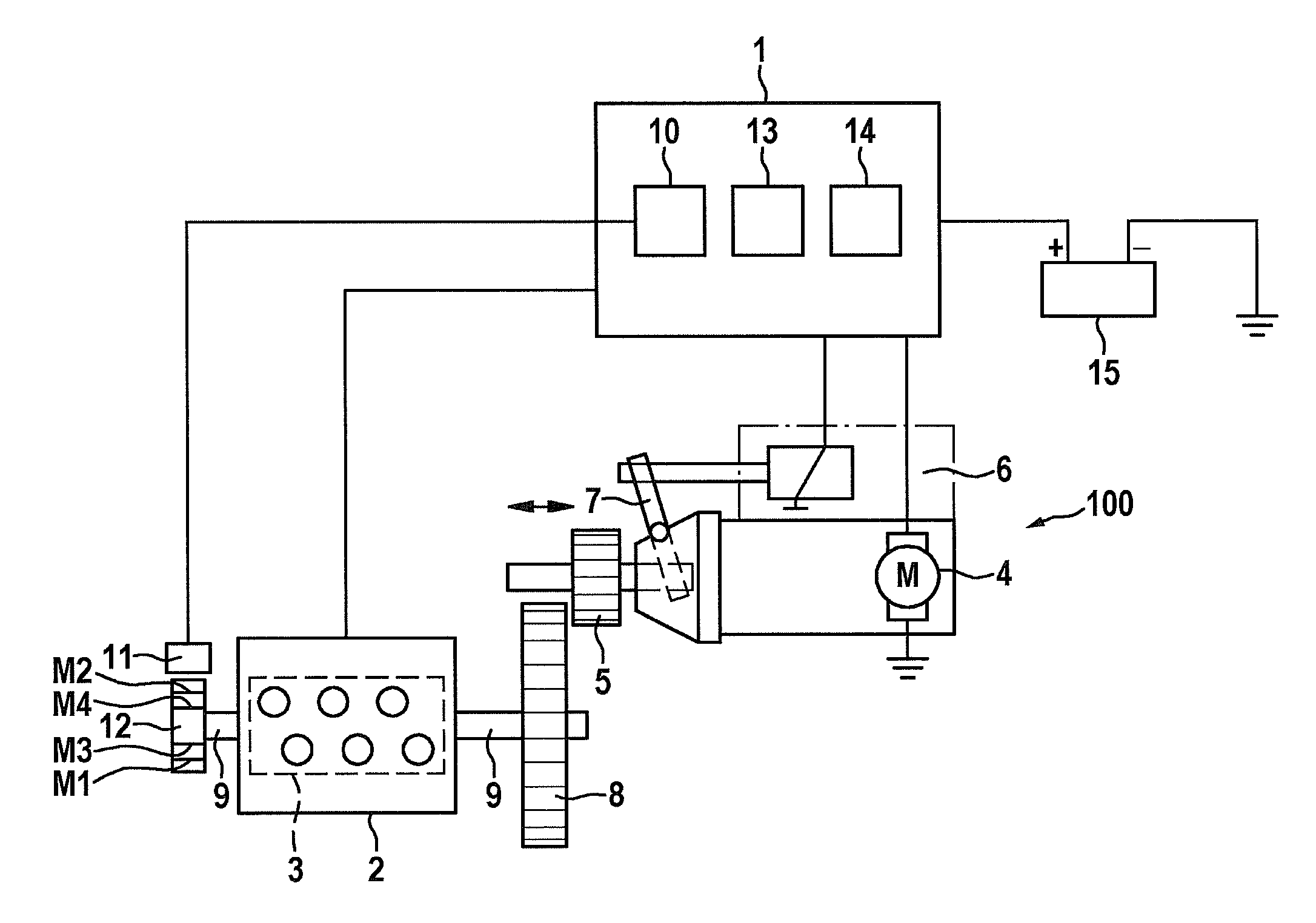
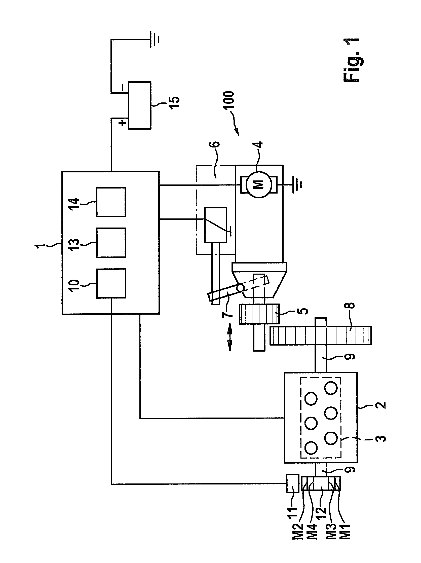
[0029]FIG. 1 shows a circuit diagram of a control system 1 for detecting the rotational speed of an internal combustion engine. Control system 1 is an engine control unit, for example, which is in informational contact and control contact with sensors and actuators of the internal combustion engine. Control system 1 also has the functions of activating a starter device 100 in a start-stop operation. For this purpose, starter device 100, including a starter motor 4 having a starter pinion 5 and a meshing device 6, is controllable by control system 1.

[0030]According to the present invention, control system 1 activates starter device 100 in such a way that starter pinion 5 meshes with an annular gear 8 of the coasting internal combustion engine 2. Starter motor 4 is therefore accelerated to a certain rotational speed and lever 7 of meshing device 6 is operated. Devices which are already present on internal combustion engine 2 are resorted to for determining rotational speed n of intern...


PUM


Abstract

A method for detecting rotational speeds (n) of an internal combustion engine having a signal wheel having marks (M1 through M7) for signaling on a crankshaft of the internal combustion engine is described. The marks (M1 through M7) on the signal wheel are detected with the aid of a sensor and evaluated by a detection and evaluation device. To implement high-precision detection of a rotational speed, the rotational speeds (n) are evaluated using a sector section of approximately 6° to 35° to increase the accuracy on the basis of a reduced sector section of the signal wheel.

Description

FIELD OF THE INVENTION[0001]The present invention relates to a method for detecting rotational speeds of a crankshaft of an internal combustion engine using a signal wheel having marks on the crankshaft, the marks on the signal wheel being detected and evaluated by a detection and evaluation device with the aid of a sensor. The present invention also relates to a computer program product and a control system having a detection device and an evaluation device including a microcomputer having a program memory.BACKGROUND INFORMATION[0002]It is known to detect the rotational speed of an internal combustion engine on a crankshaft for an engine control unit for synchronization purposes for precisely timed injection into the individual cylinders. For this purpose, the rotational movement of a gearwheel situated on the crankshaft is detected by a sensor. The gearwheel is synchronizable. At least one or two defined tooth gaps are provided for this purpose.[0003]For example, a method for rota...

Claims


Application Information

Patent Timeline
Patent Type & Authority Patents(United States)
IPC IPC(8): G01M17/00G01M15/04F02D41/00F02N11/08F02D41/04
CPCG01M15/046F02D41/009F02D41/0097F02N11/0855F02D41/042F02D2250/06
Inventor ROESSLE, MARKUSMAURITZ, EWALD
Owner SEG AUTOMOTIVE GERMANY GMBH
Why Eureka
Try Eureka