Microstructured micropillar arrays for controllable filling of a capillary pump

a microstructured micropillar array and controllable technology, applied in the direction of circuit elements, laboratory glassware, thin material processing, etc., can solve the problems of increasing the flow resistance of fluid through the channel, reducing the volume and not providing a reliable regular and controlled filling of the capillary pump

Active Publication Date: 2015-11-03
INTERUNIVERSITAIR MICRO ELECTRONICS CENT (IMEC VZW)
View PDF20 Cites 8 Cited by
  • Summary
  • Abstract
  • Description
  • Claims
  • Application Information

AI Technical Summary

Benefits of technology

[0011]According to one embodiment of the present disclosure, the capillary stop valve pins a liquid-vapor interface to prevent the propagation path of the fluid sample along an undesired direction.

Problems solved by technology

However, smaller channel dimensions result in the creation of viscous forces that result in an increase of the flow resistance of the fluid through the channel.
Therefore, there is a trade-off between high capillary pressure and low flow resistance of a fluid.
However, these solutions do not provide a reliable regular and controlled filling of the capillary pump.
An irregular and uncontrolled filling of the capillary pump results in the creation of shortcut paths of a liquid in the capillary pump, whereby the fluid finds a direct path between an inlet and an outlet of the pump, without completely filling the pump.
Further, the irregular and uncontrolled filling of the capillary pump results in the creation of air bubbles in a closed loop capillary pump resulting in a decrease of the volume of the capillary pump.

Method used


Image

  • Microstructured micropillar arrays for controllable filling of a capillary pump
  • Microstructured micropillar arrays for controllable filling of a capillary pump
  • Microstructured micropillar arrays for controllable filling of a capillary pump

Examples


Embodiment Construction

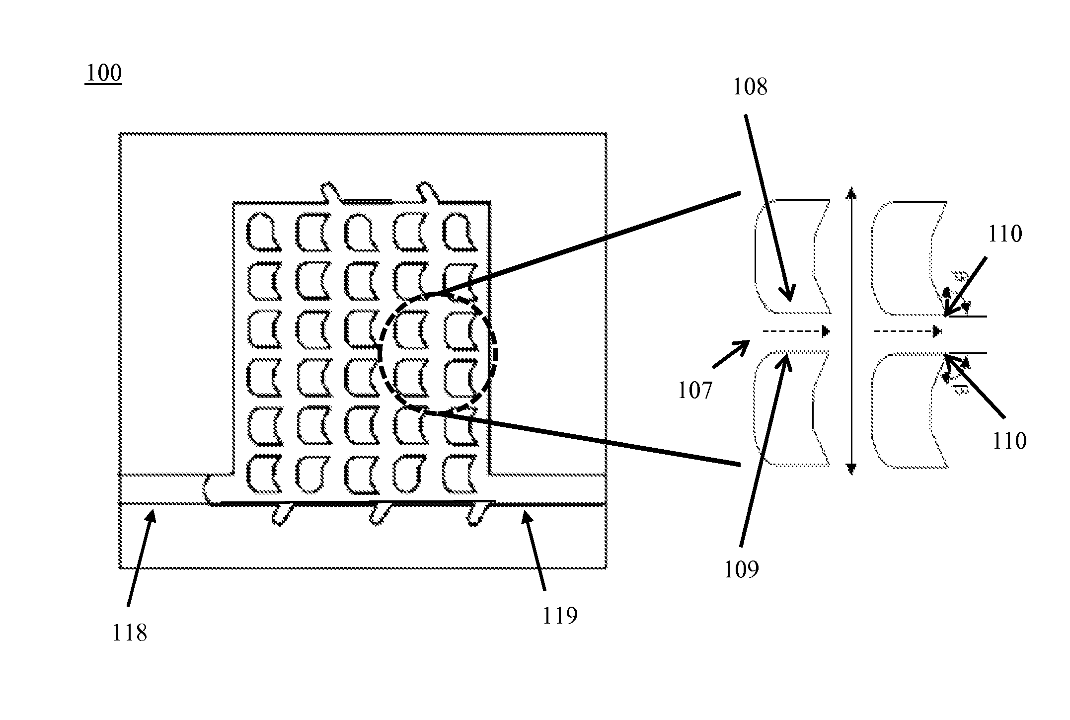
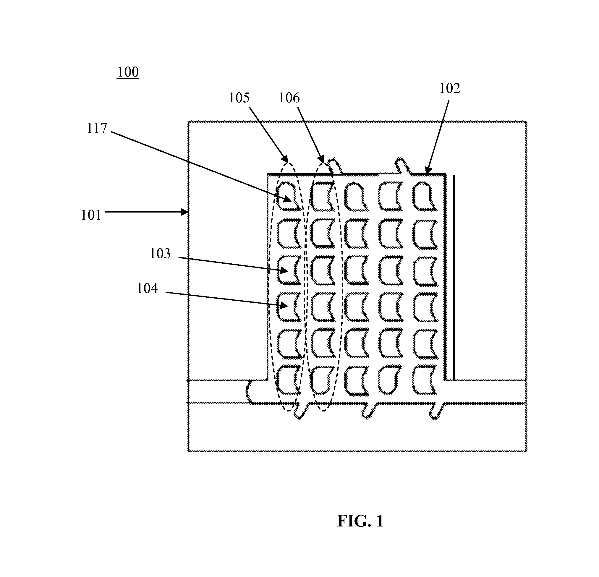
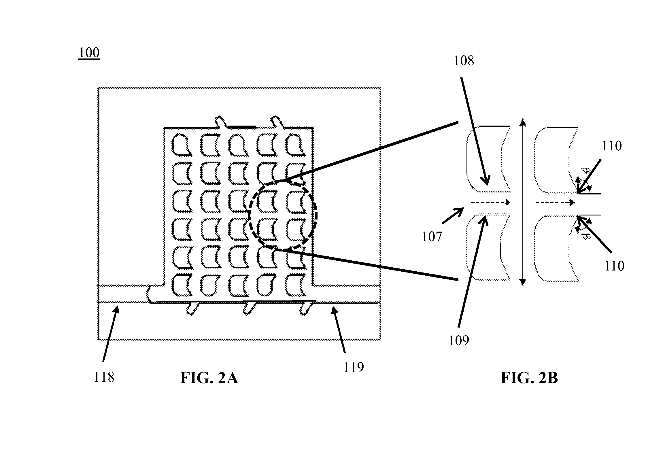
[0026]Embodiments of the present disclosure may provide a capillary pump with a controlled filling mechanism while achieving a high capillary pressure and a low flow resistance of a fluid sample in the pump.

[0027]Embodiments of the present disclosure may provide a capillary pump with a controlled filling mechanism to obtain a desired filling front in the pump.

[0028]Embodiments of the present disclosure may provide a capillary pump with a controlled filling mechanism to regulate a fluid sample flow along a desired fluid propagation path in the pump.

[0029]Embodiments of the present disclosure may provide a capillary pump with a controlled filling mechanism to obtain a column by column filling of the pump.

[0030]Embodiments of the present disclosure may provide a capillary pump with a controlled filling mechanism to obtain a row by row filling of the pump.

[0031]Embodiments of the present disclosure may provide a capillary pump with a controlled filling mechanism to obtain a desired fill...


PUM


Abstract

The embodiments of the present disclosure relate to a micro-fluidic device comprising a substrate, a cavity in the substrate and a plurality of micro-pillar columns located inside the cavity. The micro-pillars columns are configured to create a capillary action when a fluid sample is provided in the cavity. A micro-fluidic channel is present between two 5 walls of any two adjacent micro-pillars in a same micro-pillar column. Each of the two walls comprises a sharp corner along the direction of a propagation path of the fluid sample in the micro-fluidic channel thereby forming a capillary stop valve. A notch provided in a sidewall of the cavity acts as a capillary stop valve.

Description

CROSS-REFERENCE TO RELATED APPLICATION[0001]This application claims priority to European Patent Application No. 14151290. 5 filed on Jan. 15, 2014, the contents of which are hereby incorporated by referenceTECHNICAL FIELD[0002]The disclosure is related to the field of capillary micro-fluidic devices. In particular, the present disclosure relates to the field of passive pumping of fluids.BACKGROUND OF THE DISCLOSURE[0003]Typically, micro-fluidic capillary systems necessitate the use of capillary pumps. The capillary pumps have posts to create a capillary pressure inside the capillary system. An effective and efficient micro-fluidic capillary pumping system requires a high capillary pressure with a low-flow resistance. The dimensions of the posts of the capillary pump should be kept relatively small to create a high capillary pressure with a low flow resistance of the fluid.[0004]In a capillary pumping application, the capillary pressure may be represented by ΔPcap=2γ / R, wherein γ is ...

Claims


Application Information

Patent Timeline
Patent Type & Authority Patents(United States)
IPC IPC(8): F15C1/02B01L3/00
CPCB01L3/50273B01L3/502738B01L3/502746B01L2300/0838B01L2300/12B01L2400/0406B01L2400/0688Y10T137/87917
Inventor JONES, BENJAMINFIORINI
Owner INTERUNIVERSITAIR MICRO ELECTRONICS CENT (IMEC VZW)
Why Eureka
Try Eureka