Apparatus and method for isolating a section of a pipe riser bore in the course of riser renewal

a technology of riser bore and riser plate, which is applied in the direction of mechanical equipment, wellbore/well accessories, sealing/packing, etc., can solve the problems of long set-up time, weakened upper sections of upper sections, and complex tools, so as to prevent the separation of the back plate

Active Publication Date: 2015-11-10
CB CANADA ACQUISITION INC
View PDF19 Cites 7 Cited by
  • Summary
  • Abstract
  • Description
  • Claims
  • Application Information

AI Technical Summary

Benefits of technology

[0035]In a preferred optional feature, the back plate is connected by floating locking pins with the back end of the body, said pins being positioned internally of the body in bores which permit limited axial movement of the pins and back plate but the body has shoulders which prevent separation of the back plate and body. In addition, the front plate is connected with the body by locking pins which permit limited axial movement of the body toward the front plate. As a consequence of this arrangement the vent rod assembly can pull the back plate and body toward the front plate and thereby squeeze the seal elements to actuate the isolation assembly, while the locking pins still ensure cohesiveness of the isolation assembly.

Problems solved by technology

As a consequence, in many cases their upper sections have become weakened and worn by wave action, corrosion and other damaging actions.
However, we understand that they are characterized by several shortcomings, including that:the tools are complex and their use entails lengthy set-up times;the tools are not adapted to monitor and provide a real time indication of the on-going competence or possible leakage of the packer seal element; andrental of the known tools is expensive.
While these platforms are huge structures, the space available to feed an isolation tool into the open upper end of the riser bore is commonly very limited.
Dropping a steel part down the riser bore is unacceptable to the well operator.

Method used


Image

  • Apparatus and method for isolating a section of a pipe riser bore in the course of riser renewal
  • Apparatus and method for isolating a section of a pipe riser bore in the course of riser renewal
  • Apparatus and method for isolating a section of a pipe riser bore in the course of riser renewal

Examples


Embodiment Construction

[0069]Throughout the description the following terms will be assumed to have the following meanings:

[0070]“Axial”—this term is used to indicate a direction along the longitudinal axis of the pipe and tool. Thus, the term “axially extending” will be understood to mean extending in a direction parallel to the longitudinal axis of the pipe.

[0071]“Front” and “back” and “upper” and “lower”—these terms are used interchangeably to describe the positions of various components of the tool. The terms “front” and “upper” indicate a position closer to the open end of the pipe. The terms “back” and “lower” indicate a position away from the open end of the pipe.

[0072]“Ground surface” is intended to mean the off-shore platform (not shown) or an alternative surface structure adjacent the upper end of the pipe.

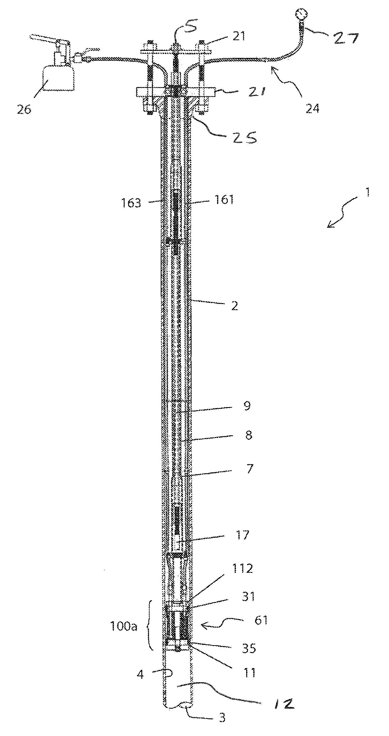
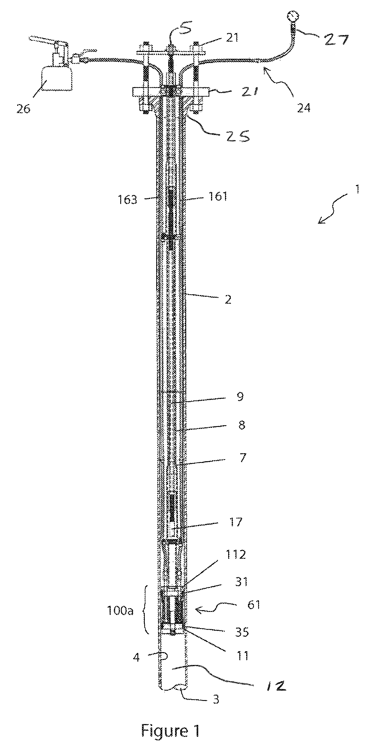
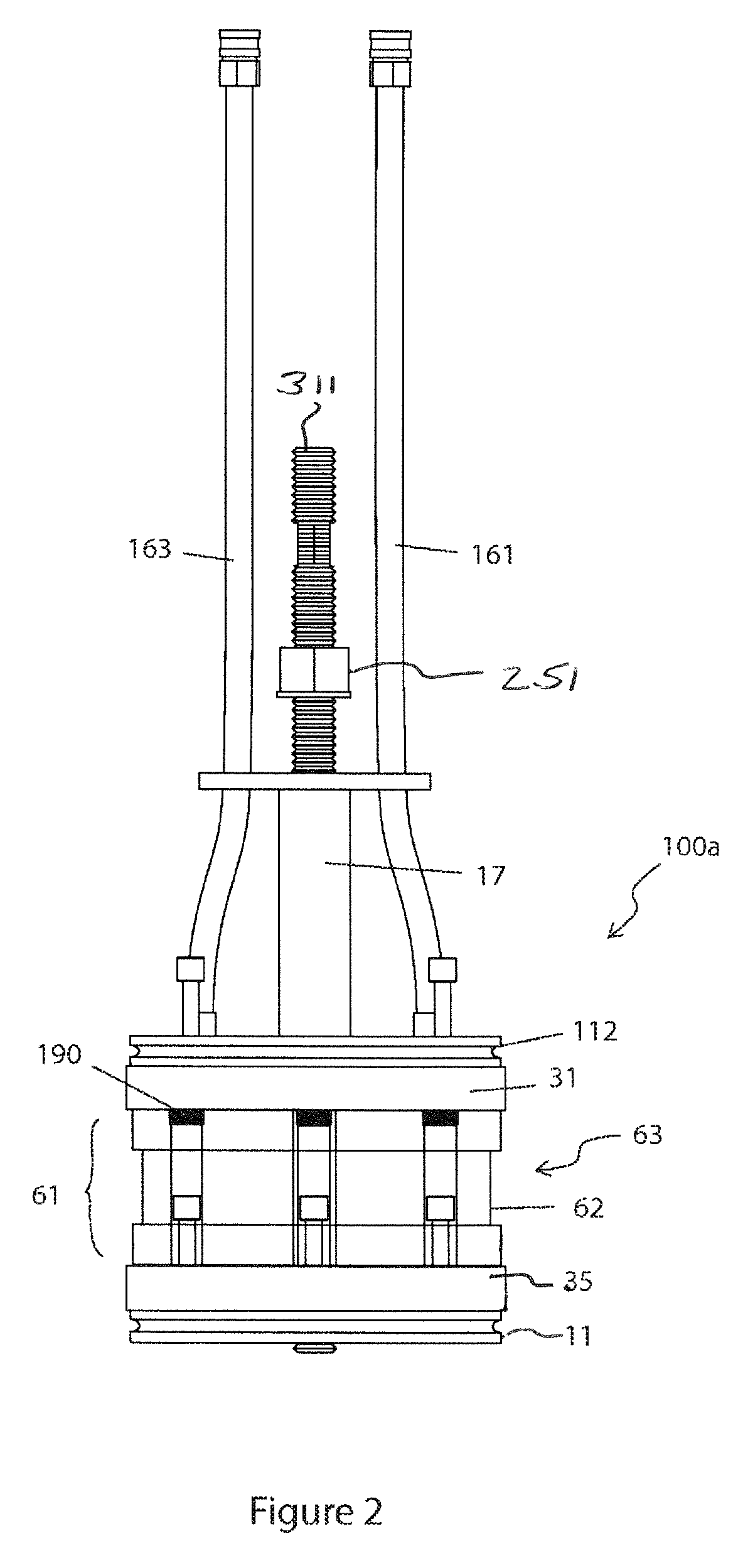
[0073]The isolation tool 1 is shown assembled and ready to operate in FIG. 1. It is illustrated in FIGS. 26-29 as inserted in an upwardly oriented pipe 2, such as an off-shore platform riser w...


PUM


Abstract

The isolation tool works at depth in the bore of a pipe whose upper end is to be severed and replaced. The tool isolates the lower pipe bore from the upper bore so that flammable downhole fluid is prevented from reaching a welding site along the pipe wall. The tool incorporates: means for establishing a pair of axially spaced apart annular seals engaging the pipe inner surface; means for venting downhole fluid to ground surface; and means for monitoring for seal leakage. The tool is primarily mechanical in nature. It finds use in connection with off-shore platform riser renewal operations.

Description

RELATED APPLICATIONS[0001]This application claims priority to U.S. Provisional Patent Application No. 61 / 809,284, filed Apr. 5, 2013, entitled “TESTING AND ISOLATING APPARATUS AND METHOD FOR RISERS,” the entirety of which is incorporated herein by reference as if set forth in full.FIELD OF THE INVENTION[0002]The invention relates to a mechanical assembly or “isolation tool” for use in controlling fluid movement through a pipe bore during the course of replacing a section of the pipe. For example, the tool may be used in connection with the process of replacing the worn or damaged upper section of a vertical “riser” associated with an off-shore oil or gas production platform. The invention further relates to a method associated with the pipe section replacement procedure.BACKGROUND OF THE INVENTION[0003]The invention was developed in connection with providing an isolation tool which could be used ‘downhole’ in connection with the process of replacing the upper section of an upwardly ...

Claims


Application Information

Patent Timeline
Patent Type & Authority Patents(United States)
IPC IPC(8): E21B33/12E21B33/128E21B23/00E21B41/00
CPCE21B41/0007E21B33/12E21B33/128E21B17/01E21B29/00E21B33/124F16L55/132
Inventor BERUBE, GUYBROWN, GRAHAM T.BLAIR, TOM
Owner CB CANADA ACQUISITION INC
Why Eureka
Try Eureka