Active thermal protection for switches

a technology of active thermal protection and switch, applied in the field of electronic devices, can solve the problems of flickering instability, power loss of all switching power converters, and problems with the lighting system,

Active Publication Date: 2015-11-10
SIGNIFY HLDG BV
View PDF52 Cites 3 Cited by
  • Summary
  • Abstract
  • Description
  • Claims
  • Application Information

AI Technical Summary

Benefits of technology

[0016]In one embodiment of the present invention, a method includes controlling conductivity of a switch and estimating an amount of power dissipated by the switch. The method further includes determining if the estimated power dissipated by the switch exceeds a first predetermined threshold value and reducing the power dissipated by the switch when the estimated power dissipated by the switch exceeds the first predetermined threshold value.
[0017]In another embodiment of the present invention, an apparatus includes a controller, and the controller is configured to control conductivity of a switch and estimate an amount of power dissipated by the switch. The controller is further configured to determine if the estimated power dissipated by the switch exceeds a first predetermined threshold value and reduce the power dissipated by the switch when the estimated power dissipated by the switch exceeds the first predetermined threshold value.
[0018]In a further embodiment of the present invention, an apparatus includes a switching power converter having a switch whose conductivity controls power conversion by the switching power converter. The apparatus further includes a load coupled to the switching power converter and a controller. The controller is configured to control conductivity of a switch and estimate an amount of power dissipated by the switch. The controller is further configured to determine if the estimated power dissipated by the switch exceeds a first predetermined threshold value and reduce the power dissipated by the switch when the estimated power dissipated by the switch exceeds the first predetermined threshold value.

Problems solved by technology

All switching power converters have some inherent power losses due to, for example, non-ideal component characteristics.
Premature disconnects can cause problems with the lighting system, such as flicker and instability.
Because of component non-idealities, the switching power converter 108 includes inherent power losses.
However, circuits are generally designed to minimize inherent power losses, and these inherent power losses are often negligible and, thus, insufficient to dissipate enough power to compensate for the difference between the POWER IN and the POWER OUT+PINH at some POWER OUT levels.

Method used


Image

  • Active thermal protection for switches
  • Active thermal protection for switches
  • Active thermal protection for switches

Examples


Embodiment Construction

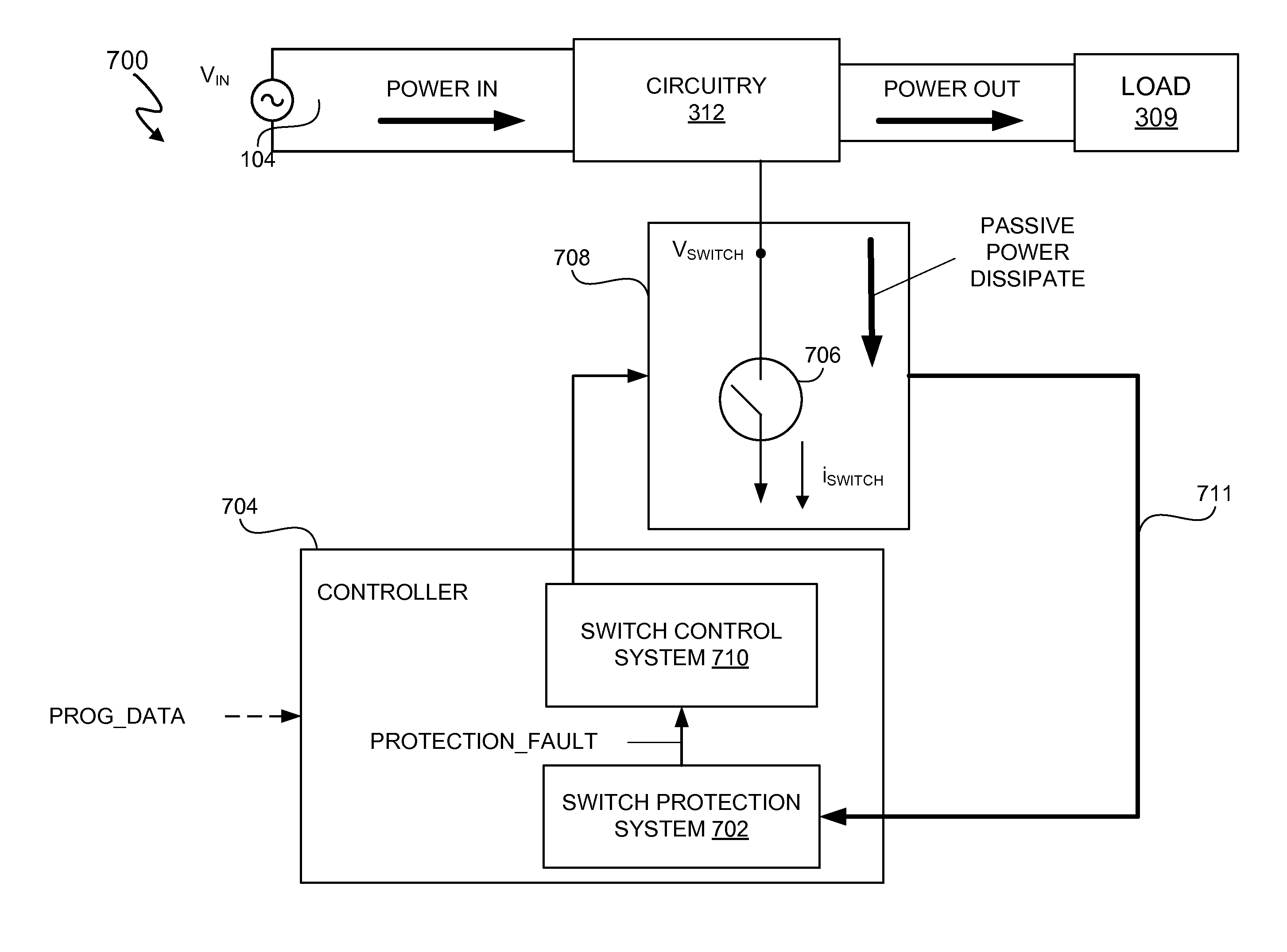
[0029]A system and method include a controller that reduces power dissipated by a switch when an estimated amount of power dissipated by the switch exceeds a predetermined threshold. In at least one embodiment, reducing the power dissipated by the switch prevents damage to the switch due to thermal effects of overheating. In at least one embodiment, the controller determines the estimated amount of power dissipated by the switch using actual drain-to-source current and drain voltage data. In at least one embodiment, the controller includes a fail-safe, estimated power dissipation determination path that activates when the drain voltage data fails a reliability test.

[0030]Additionally, in at least one embodiment, the controller includes a model of thermal characteristics of the switch. In at least one embodiment, the controller utilizes real-time estimated power dissipation by the switch and the model to determine when the estimated power dissipated by the switch exceeds a power diss...


PUM


Abstract

A system and method include a controller that reduces power dissipated by a switch, such as a source-controlled field effect transistor, when an estimated amount of power dissipated by the switch exceeds a predetermined threshold. Reducing the power dissipated by the switch prevents damage to the switch due to overheating. The controller determines the estimated amount of power dissipated by the switch using actual drain-to-source current and drain voltage data. In at least one embodiment, the controller includes a fail-safe, estimated power dissipation determination path that activates when the drain voltage data fails a reliability test. Additionally, in at least one embodiment, the controller includes a model of thermal characteristics of the switch. In at least one embodiment, the controller utilizes real-time estimated power dissipation by the switch and the model to determine when the estimated power dissipated by the switch exceeds a power dissipation protection threshold.

Description

CROSS-REFERENCE TO RELATED APPLICATION[0001]This application claims the benefit under 35 U.S.C. §119(e) and 37 C.F.R. §1.78 of U.S. Provisional Application No. 61 / 675,399 filed on Jul. 25, 2012, which is incorporated by reference in its entirety.BACKGROUND OF THE INVENTION[0002]1. Field of the Invention[0003]The present invention relates in general to the field of electronics, and more specifically to a system and method that provides thermal protection for switches.[0004]2. Description of the Related Art[0005]Switching power converters convert power received from a power source, such as a voltage supply, into power suitable for a load. The power received from the voltage supply is referred to as “POWER IN”, and the power provided to the load is referred to as “POWER OUT”. All switching power converters have some inherent power losses due to, for example, non-ideal component characteristics. Such inherent power losses tend to be minimized so as to increase the efficiency of the swit...

Claims


Application Information

Patent Timeline
Patent Type & Authority Patents(United States)
IPC IPC(8): H05B37/02H05B33/08H03K17/14H05B41/36H05B39/04H02M3/335H05B44/00
CPCH02M3/33523H03K17/145H05B33/0815H05B33/0848H05B33/0884Y02B20/341Y10T307/406Y10T307/832H05B45/14Y02B20/30H05B45/3725H05B45/385H05B47/24H02M3/335
Inventor SOOD, MOHITISAACSON, SPENCERSINGH, RAHULHE, ZHAOHUI
Owner SIGNIFY HLDG BV
Why Eureka
Try Eureka