Low diffusivity barrier fluid packing system

a technology of fluid packing and low diffusivity, which is applied in the direction of valve operating means/release devices, valve bends, transportation and packaging, etc., can solve the problems of the valve stem sticking to the stem, the packing system, and the valve stem being susceptible to varying levels of leakage, so as to reduce the leakage level, reduce the voc emission, and limit the diffusivity of gas

Active Publication Date: 2015-11-17
CONTROL COMPONENTS INC
View PDF17 Cites 5 Cited by
  • Summary
  • Abstract
  • Description
  • Claims
  • Application Information

AI Technical Summary

Benefits of technology

[0011]In accordance with the present invention, there is provided a fluid or liquid barrier packing system which is adapted to minimize VOC emissions, while also providing live-loading and continuous load monitoring functions. The components of the packing system (including the liquid barrier) are adapted to be installed in a traditional stuffing box of a valve utilizing a top entry method, and without the necessity of having to inject the liquid through any lateral side port(s) within the bonnet of the valve. In this regard, the packing system of the present invention has a simplified construction and does not rely upon the use of external components, thus eliminating many of the complexities of prior art approaches, as well as the need for any external pumps to inject the fluid or liquid into the valve at high pressures. Further, the packing system of the present invention reduces leakage levels as required by low emission leakage standards and specifications by creating a reverse osmosis effect, limiting the diffusivity of a gas through the packing elements of the system. Thus, the packing system of the present invention provides a simplified method to load and monitor a barrier in the stuffing box of the valve to slightly higher pressure than processed fluid pressure.
[0012]As indicated above, the packing system of the present invention is provided with, among other things, live-loading and a continuous load monitoring system. The packing system also makes use of a valve stem having a hard coated and super-finish stem coating, and is specifically configured to reduce wear, friction on valve seals, and to further keep the packing under continuous load to satisfy very low fugitive emission leakage standards. The hard coated and super-finish stem coating of the valve stem used in conjunction with the packing system of the present invention is instrumental in reducing wear and friction of the seals. These features minimize packing leakage and barrier fluid loss resulting in significant leakage reduction, while at the same time increasing the longevity of the packing system once in service. In one embodiment of the present invention, spring live loading is installed into the stuffing box of the valve via a top entry method, thus reducing the number of components and facilitating ease of assembly.

Problems solved by technology

Alternatively, if the volume of the packing material increases (which can happen with certain packing materials), the radial pressure of the stem in an unsprung valve could increase too much, thus possibly causing sticking of the stem.
However, the packing system included in many valve designs, including those which include a live-loaded packing as described above, is still often susceptible to varying levels leakage about the valve stem.
Though some solutions have been developed which make use of a barrier fluid, these particular solutions do not provide a live loaded system to maintain the barrier fluid pressure at a level higher than that of the process pressure, thus diminishing the longevity of the packing integrity once in service conditions (see, e.g., U.S. Pat. No. 7,118,114).
However, in this particular solution, the grease is typically lost after repeated valve cycling, with its efficacy as a fluid barrier thus only being somewhat temporary unless replenished on a frequent basis.
As will be recognized, a loss of efficacy of the grease as a fluid barrier prior to replenishment may result in undesirable leakage.
Further, the attempted replenishment of the grease while the valve is still pressurized can jeopardize the integrity of the valve packing, thus creating a potential hazard to operators if high pressure gas escapes the valve bonnet.
In addition, the use of the aforementioned lateral injection technique gives rise to the potential for lateral grease escape during the operation of the valve, thus creating a possible leak source.
Still further, the aforementioned solution, as currently known, lacks modalities for detecting when the grease level is falling to an ineffective level.
Other solutions are relatively complex to manufacture, assemble and service.
Further, the existing solutions typically ignore the role of a seal to shaft interface in friction and seal wear, and the resultant impact on leakage levels.

Method used


Image

  • Low diffusivity barrier fluid packing system
  • Low diffusivity barrier fluid packing system
  • Low diffusivity barrier fluid packing system

Examples


first embodiment

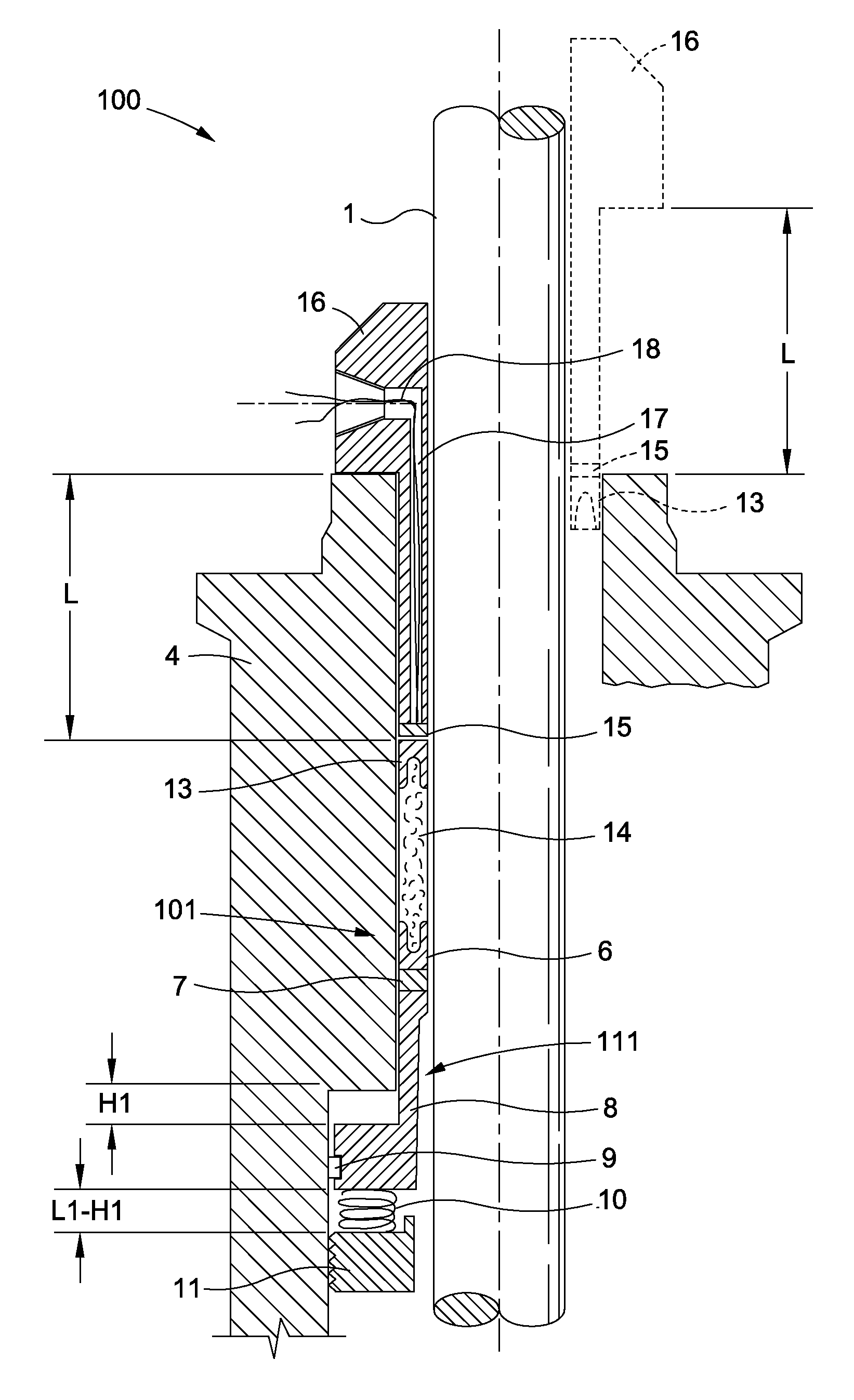
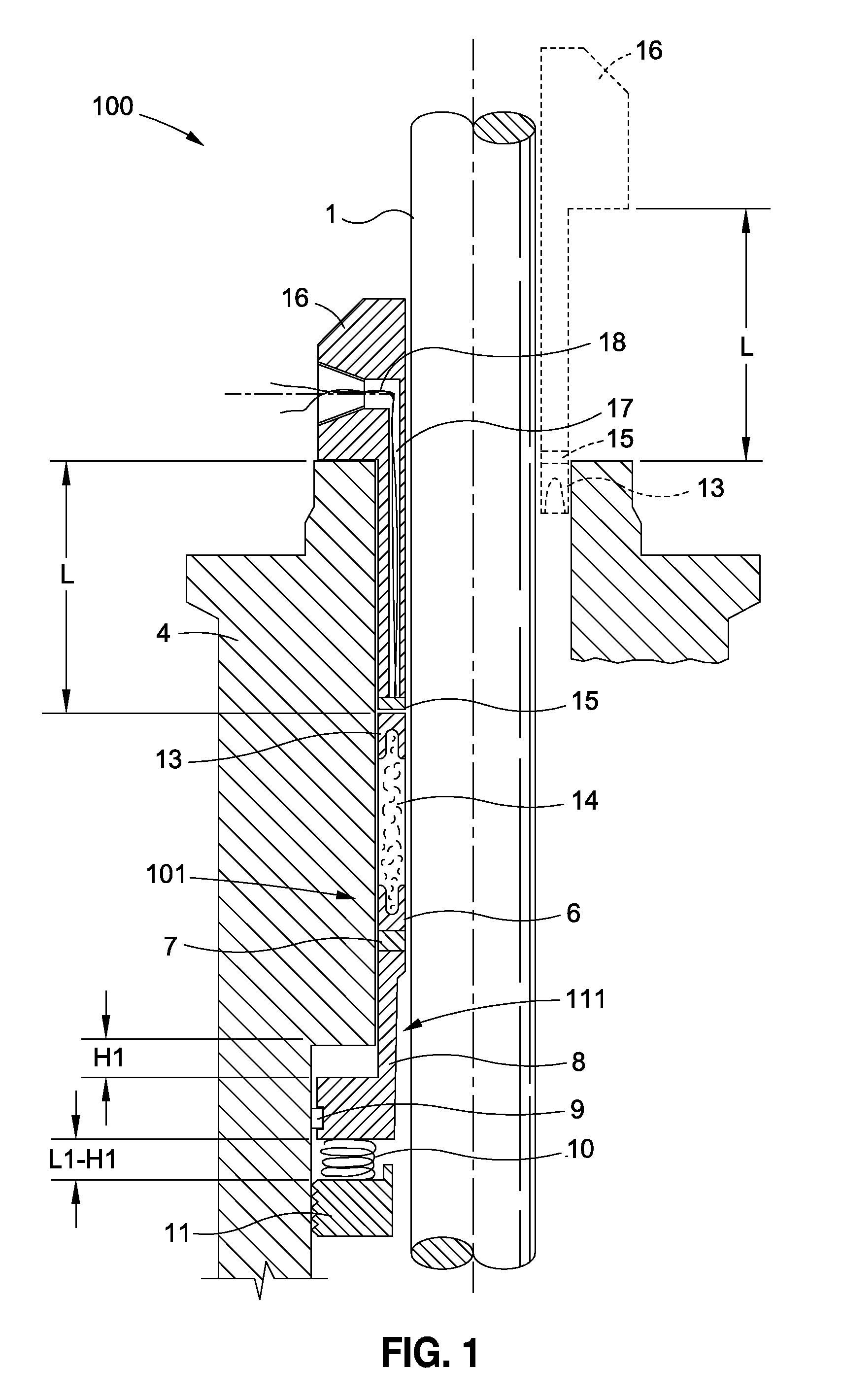
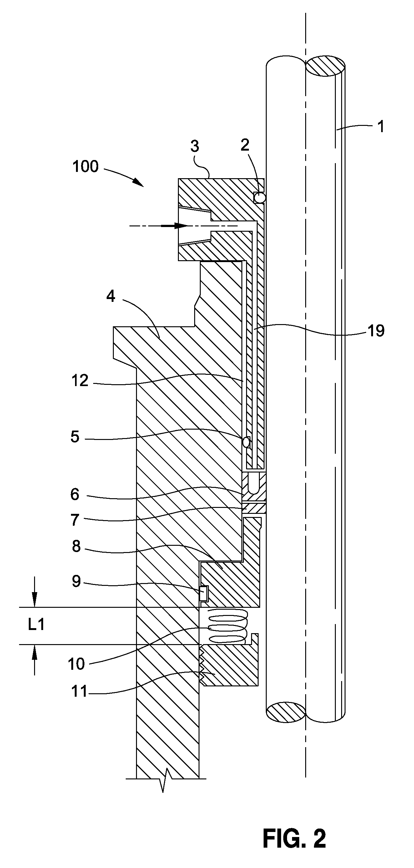
[0020]Referring now to the drawings wherein the showings are for purposes of illustrating preferred embodiments of the present invention only, and not for purposes of limiting the same, FIGS. 1 and 2 partially depict an exemplary valve 100 which includes a low fugitive emission, fluid or liquid barrier packing system 101 constructed in accordance with the present invention. The exemplary valve 100 having the packing system 101 integrated therein possesses certain structural features. More particularly, the valve 100 includes a body, which itself comprises a valve bonnet 4. Extending axially through the valve bonnet 4 is a central passageway 12. As seen in FIGS. 1 and 2, the passageway 12 extending through the valve bonnet 4 is not of uniform inner diameter. Rather, the passageway 12 is divided into an upper section which is of the first inner diameter, and a lower section which is of a second inner diameter exceeding that of the upper section. As a result, the upper and lower sectio...

second embodiment

[0025]The packing system 101 further comprises an annular load sensor or load cell 15 which is positioned upon and directly abuts the upper packing 13. As such, the load cell 15 also resides within the upper section of the passageway 12 within the annular gap defined between the valve stem 1 and the valve bonnet 4. The load cell 15 is effectively captured between the upper packing 13 and a packing follower 16 which is also included in the packing system 101. As seen in and as viewed from the perspective shown in FIG. 1, the packing follower 16 includes an annular upper section which is of a first outer diameter, and a tubular lower section which protrudes from the upper section and is of a second outer diameter less than that of the first outer diameter of the upper section. As a result, the upper and lower sections of the packing follower 16 are separated by an annular shoulder. The lower section is also of the length L shown in FIG. 1. The packing follower 16 further defines a cen...


PUM

PropertyMeasurementUnit
pressureaaaaaaaaaa
viscousaaaaaaaaaa
outer diameteraaaaaaaaaa

Abstract

In accordance with the present invention, there is provided a fluid or liquid barrier packing system which is adapted to minimize VOC emissions, while also providing live-loading and continuous load monitoring functions. The components of the packing system (including the liquid barrier) are adapted to be installed in a traditional stuffing box of a valve utilizing a top entry method, and without the necessity of having to inject the liquid through any side ports of the valve. The packing system reduces leakage levels as required by low emission leakage specifications by creating a reverse osmosis effect, limiting the diffusivity of a gas through the packing elements of the system. Thus, the packing system of the present invention provides a simplified method to load and monitor a barrier in the stuffing box of the valve to slightly higher pressure than processed fluid pressure.

Description

CROSS-REFERENCE TO RELATED APPLICATIONS[0001]The present application claims priority to U.S. Provisional Patent Application Ser. No. 61 / 644,269 entitled LOW DIFFUSIVITY BARRIER FLUID PACKING SYSTEM filed May 8, 2012.STATEMENT RE: FEDERALLY SPONSORED RESEARCH / DEVELOPMENT[0002]Not ApplicableBACKGROUND OF THE INVENTION[0003]1. Field of the Invention[0004]The present invention relates generally to valves and, more particularly, to a liquid barrier packing system adapted for integration into a valve and operative to satisfy very low fugitive emission leakage standards.[0005]2. Description of the Related Art[0006]In a typical valve construction, a valve stem may undergo a turning or sliding movement, or a combination of both movements, within its sleeve during the process of the valve moving between its open and closed configurations. In this regard, the sealing of the stem must be adequate to contend with such movement, while at the same time ensuring maintenance of fluid tightness again...

Claims


Application Information

Patent Timeline
Patent Type & Authority Patents(United States)
IPC IPC(8): F16K31/14F16J15/32F16K41/02F16K41/00F16K51/00F16J15/18
CPCF16K51/00F16J15/181F16J15/186F16J15/3296F16K41/003F16K41/02Y10T137/4471F16J15/182
Inventor GIOVE, FABIOABRAHIMZADEH, JALAL
Owner CONTROL COMPONENTS INC
Why Eureka
Try Eureka