
Air-conditioning system and use thereof

a technology of air-conditioning system and air-conditioning system, which is applied in the field of air-conditioning system, can solve the problems of reducing the mass transfer of the membrane contactor or even obstructing the desiccant flow, difficult to remove water from the desiccant flow, and complicated operation, etc., and achieves the effect of making more easily

Inactive Publication Date: 2015-11-17
2NDAIR
View PDF15 Cites 25 Cited by
  • Summary
  • Abstract
  • Description
  • Claims
  • Application Information

AI Technical Summary

Benefits of technology

[0013]It is therefore a first object of the invention to provide an improved air-conditioning system with modules that may be made more easily but still meeting the requirements of stable and robust operation.

Problems solved by technology

Schematic diagrams hereof look rather simple, though the understanding of the operation is rather complex.
An additional complicating factor resides in the desiccant flow: if the solution of desiccant becomes too concentrated, crystals may develop which may reduce the mass transfer in the membrane contactor or even obstruct the desiccant flow.
This known solution however is disadvantageous energetically, as it is very hard to remove again water from the desiccant flow once needed.
Moreover, the addition of water is effectively a thinning of the desiccant flow, but it is not evident to obtain a homogeneous solution quickly.
This reduces the overall both heat and mass transfer efficiency relative to a countercurrent flow design.
Due to the small wall thickness of the plates (0.1-0.3 mm), this was delicate according to the 2006 report.
The delicate multi-step manufacturing is a clear disadvantage of the modules used by Conde.

Method used


Image

  • Air-conditioning system and use thereof
  • Air-conditioning system and use thereof
  • Air-conditioning system and use thereof

Examples


Embodiment Construction

[0047]The figures are merely intended for illustrative purposes and not drawn to scale. Equal reference numerals in different figures refer to equal or similar elements.

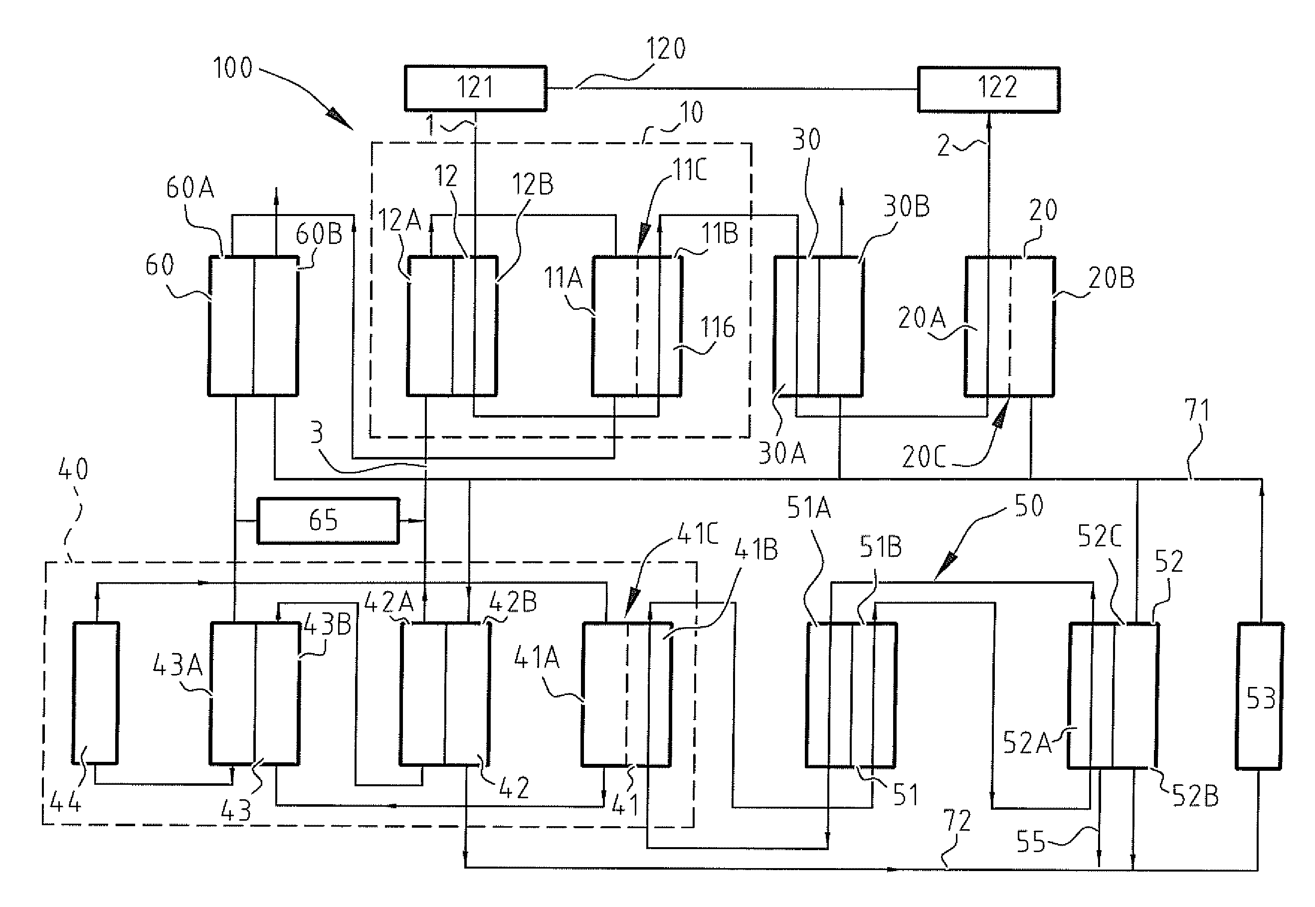
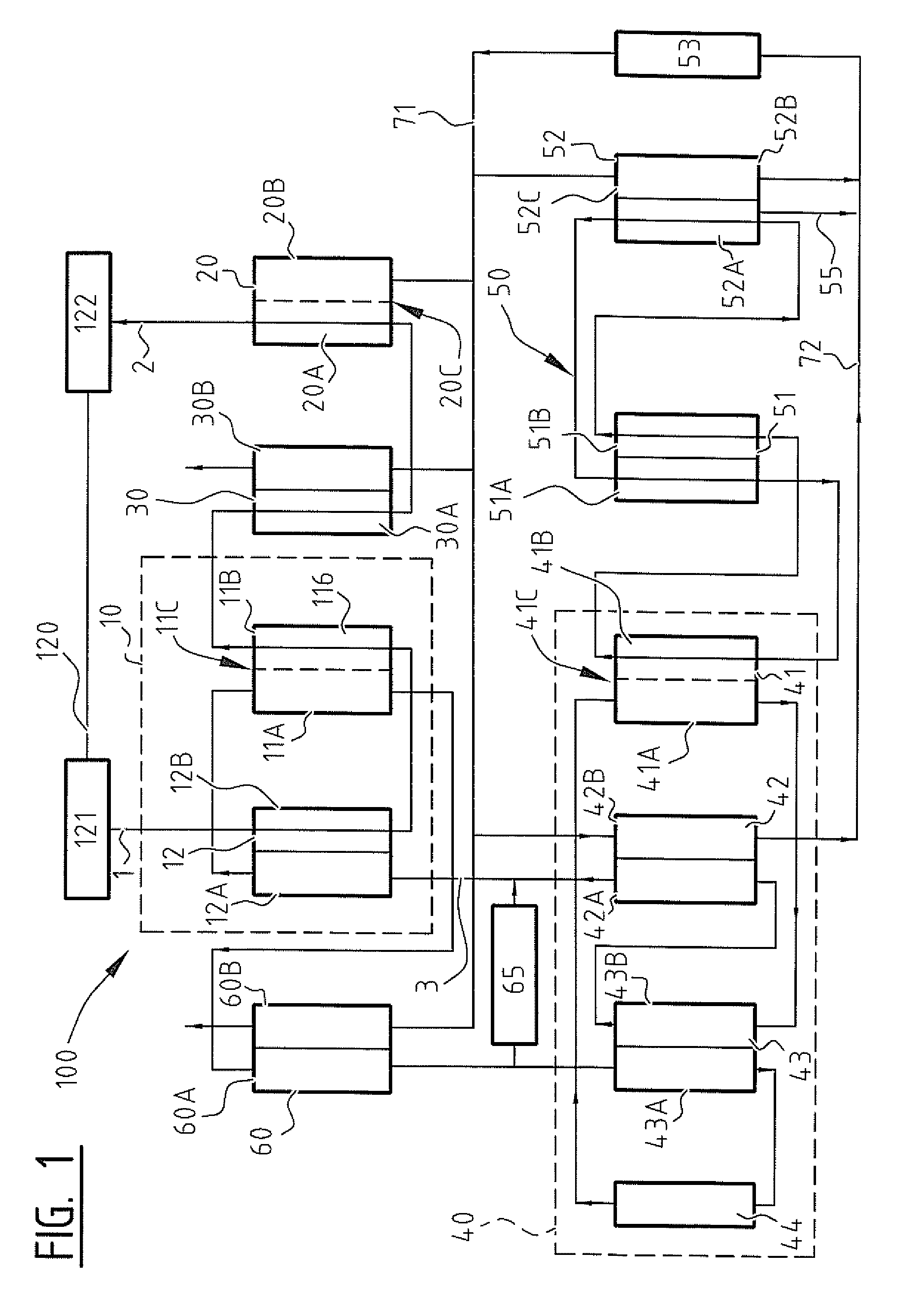
[0048]FIG. 1 shows a diagrammatical architecture of the air-conditioning system 100 according to a first embodiment.

[0049]The air-conditioning system 100 of the invention comprises most generically a dryer module 10, a humidifier module 20 and a regenerator module 40. In the example shown in

[0050]FIG. 1, furthermore a heat exchanger module 30, a heat exchanger 60, a bypass module 65, a gas system 50 and conductors for cooling liquid 71, 72 are present.

[0051]In operation, the air-conditioning system 100 draws an air volume 121 from a room 120. This typically occurs in a continuous manner, although batch-wise operation is not excluded. In such a case of batch-wise operation, the air volume 120 enters a chamber that is subsequently emptied into the air-conditioning system 100. The air volume thus forms an air flow that ...


PUM


Abstract

The air-conditioning system comprises a dryer (10) comprising a membrane contactor (11) provided with a first channel (11b) for air flow and a second channel (11a) for desiccant flow, which channels are separated through a membrane (11c). The air conditioning system further comprises a humidifier (20) comprising a membrane contactor. The air flow passes in operation the dryer (10) and the humidifier (30) between an inlet (121) and an outlet (122). The dryer (10) comprises a series connection of a heat exchanger (12) and the membrane contactor (11), which heat exchanger couples air flow from the inlet (121) with desiccant flow from a regenerator (40) and in which membrane contactor (11) the thus heat-exchanged air flow and the heat-exchanged desiccant flow are coupled for drying of the airflow.

Description

RELATED APPLICATION DATA[0001]This application is a National Stage Application under 35 U.S.C. 371 of co-pending PCT application PCT / NL2013 / 050634 designating the United States and filed Sep. 2, 2013; which claims the benefit of Dutch patent application number 2009415 and filed Sep. 4, 2012 each of which are hereby incorporated by reference in their entireties.FIELD OF THE INVENTION[0002]The invention relates to an air-conditioning system comprising:[0003]a dryer comprising a membrane contactor provided with a first channel for air flow and a second channel for desiccant flow, which channels are separated through a membrane;[0004]a humidifier comprising a membrane contactor provided with a first channel for air flow and a second channel for an aqueous liquid, which channels are separated through a membrane,[0005]a regenerator for regenerating the desiccant flow,which air flow passes in operation the dryer and the humidifier between an inlet and an outlet and which desiccant flow run...

Claims


Application Information

Patent Timeline
Patent Type & Authority Patents(United States)
IPC IPC(8): F24F3/14F24F6/02B01D53/26
CPCF24F3/14B01D53/263B01D53/268F24F3/1411F24F3/1417F24F6/02F24F2003/1435F24F2003/1458
Inventor WARMERDAM, THOMAS PETRUS HENDRICUSHERNANDEZ-MARIN, SERGIOHOLLERING, ROBERTUS WILHELMUS JACOBUS
Owner 2NDAIR
Learn More