
Tire repair device

a tire and tyre technology, applied in the field of tire repair tools, can solve the problems of insufficient tire sealant injected into the tire, inability to achieve effective tire repairing, and inability to place the tire repair sprayer upside down, etc., to achieve cost-effective, simple structure, and easy operation

Active Publication Date: 2015-11-24
TOP ALLIANCE TECH
View PDF25 Cites 10 Cited by
  • Summary
  • Abstract
  • Description
  • Claims
  • Application Information

AI Technical Summary

Benefits of technology

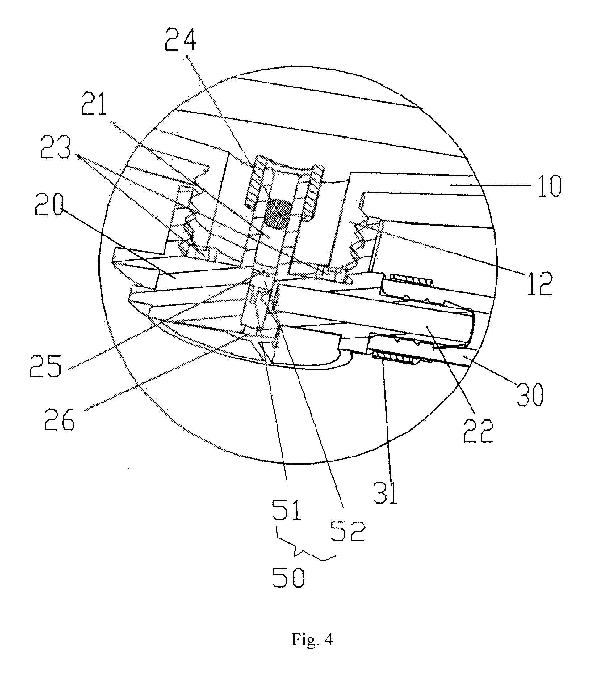
[0014]The following advantageous effects of the present application can be achieved: by applying the bottle cap with the tire sealant guiding tube, and depositing the flange and the plug within the first tube section of the tire sealant guiding tube, the plug can move in the first tube section under the influence of the air pressure in the bottle body to block or unblock the second inlet according to requirements. When no compressed air is applied into the bottle body, the plug is located between the first inlet of the first tube section and the flange of the first tube section. When air expansion inside the bottle body caused by temperature change occurs, the plug is locked on the flange. When compressed air is applied into the bottle body, the plug is located at a position of the first tube section between the second inlet and the first bottom end, so that the tire sealant flows from the bottle body to a damaged tire via the fluid transfer tube. Thus, the supply of tire sealant to the damaged tire can be achieved by changing the air pressure in the bottle body for tire repairing. Therefore, the tire repair device of the present application has a simple structure, is easy to operate, and is cost-effective; besides, the tire repair device can be used either upright or upside-down, which is good for promotion and implementation.
of the present application can be achieved: by applying the bottle cap with the tire sealant guiding tube, and depositing the flange and the plug within the first tube section of the tire sealant guiding tube, the plug can move in the first tube section under the influence of the air pressure in the bottle body to block or unblock the second inlet according to requirements. When no compressed air is applied into the bottle body, the plug is located between the first inlet of the first tube section and the flange of the first tube section. When air expansion inside the bottle body caused by temperature change occurs, the plug is locked on the flange. When compressed air is applied into the bottle body, the plug is located at a position of the first tube section between the second inlet and the first bottom end, so that the tire sealant flows from the bottle body to a damaged tire via the fluid transfer tube. Thus, the supply of tire sealant to the damaged tire can be achieved by changing the air pressure in the bottle body for tire repairing. Therefore, the tire repair device of the present application has a simple structure, is easy to operate, and is cost-effective; besides, the tire repair device can be used either upright or upside-down, which is good for promotion and implementation.

Problems solved by technology

Due to insufficient strength of human fingers applied to the sprayer in the pressing process, the tire sealant injected into the tire is not much enough.
In that way, effective tire repairing cannot be obtained.
Moreover, the tire repair sprayer cannot work when placed upside down.
That is, if the gas filling nozzle is reversed to the direction of the tire repair sprayer normally placed, the tire repairing cannot be achieved.

Method used


Image

  • Tire repair device
  • Tire repair device
  • Tire repair device

Examples


Embodiment Construction

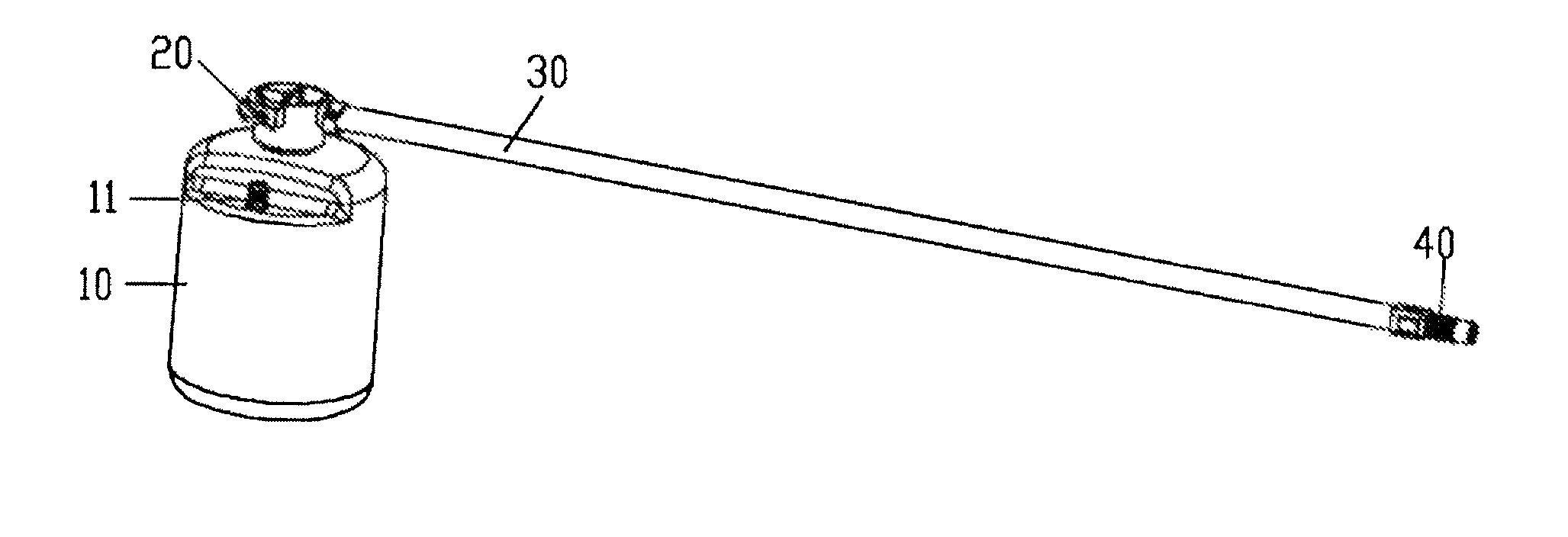
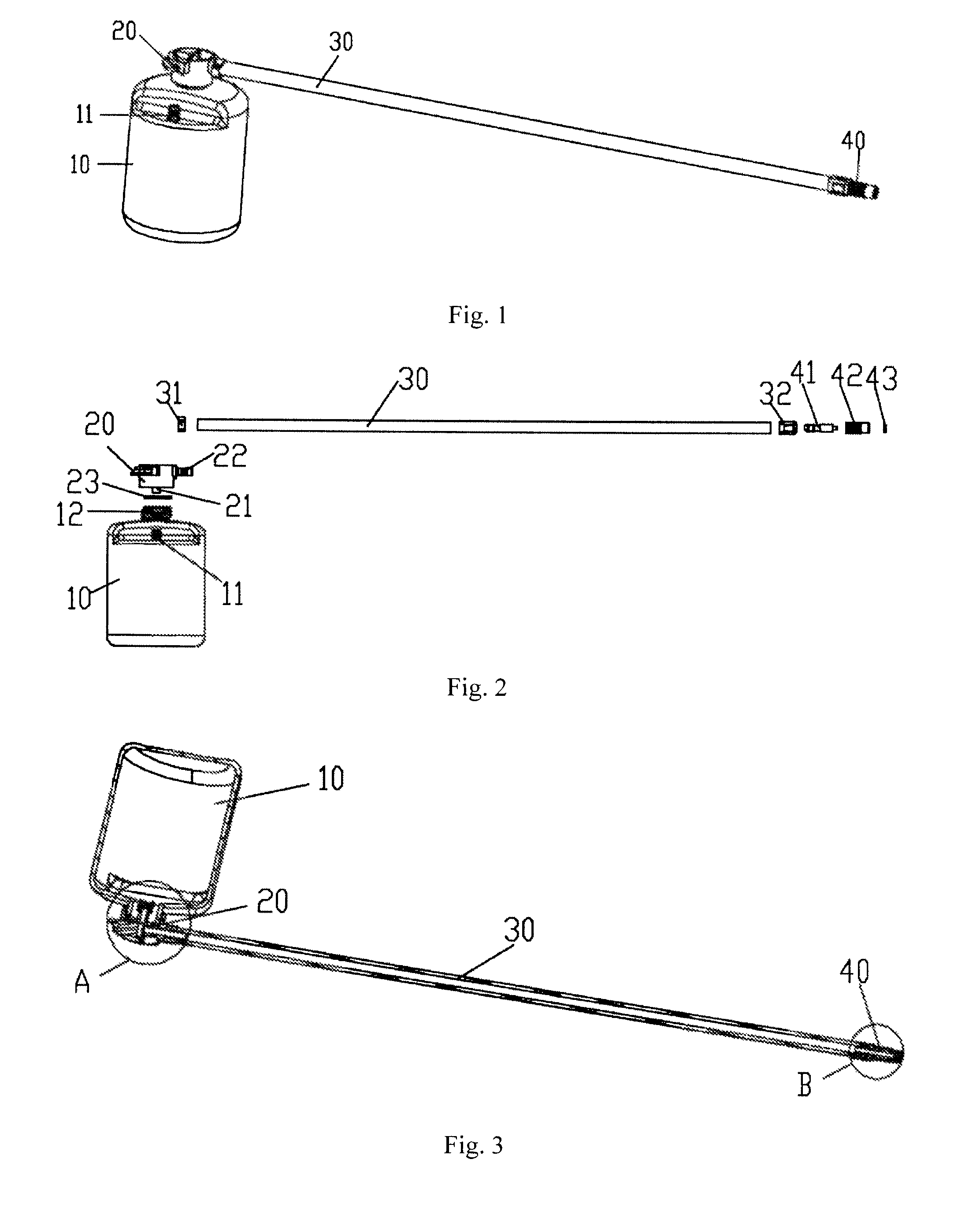
[0031]A structural schematic view of a tire repair device in accordance with a preferred embodiment of the present application is shown in FIG. 1, with more details in FIGS. 2-9. The tire repair device comprises a bottle body 10 for containing tire sealant. A bottle cap 20 is deposited at an opening of the bottle body 10 to seal the bottle body 10; and a tire sealant guiding tube is provided in the bottle cap 20. The tire sealant guiding tube includes a first tube section 21 extending into the bottle body 10, and a second tube section 22. Advantageously, in this embodiment, the second tube section 22 is perpendicular to the first tube section 21.

[0032]One end of the first tube section 21 defines a first inlet 211 configured to allow the tire sealant in the bottle body 10 to enter the first tube section 21, and the other end of the first tube section 21 is a sealed first bottom end 212. One end of the second tube section 22 defines a second inlet 221 configured to allow the tire seal...


PUM

PropertyMeasurementUnit
internal diameteraaaaaaaaaa

Abstract

A tire repair device comprises a bottle body for containing tire sealant and a bottle cap deposited at an opening of the bottle body to seal the bottle body; wherein the tire repair device further comprises a tire sealant guiding tube provided in the bottle cap, and the tire sealant guiding tube includes a first tube section extending into the bottle body and a second tube section; a flange is formed on an internal surface of the first tube section; a plug is slidably placed in the first tube section; at least one rib is fixed in the first tube section and is deposited between the flange and the first bottom end. The tire repair device of the present application has a simple structure, is easy to operate, and is cost-effective; besides, the tire repair device can be used either upright or upside-down, which is good for promotion and implementation.

Description

FIELD OF THE INVENTION[0001]The present application relates to tire repair tools, and more particularly relates to a tire repair device.BACKGROUND OF THE INVENTION[0002]Currently, tire repair devices on sale in the market can normally provide preventative functions, including automotive tire repairing and leakage proof. However, a spray-type tire sealant is usually adopted in the tire repair device in the prior art. In this case, a spray nozzle of a tire repair sprayer will be connected to a gas filling nozzle configured on the tire; by pressing the sprayer, the tire sealant can be injected into the tire. During operation process, human fingers are required to press the tire repair sprayer to make it work. Due to insufficient strength of human fingers applied to the sprayer in the pressing process, the tire sealant injected into the tire is not much enough. In that way, effective tire repairing cannot be obtained. Moreover, the tire repair sprayer cannot work when placed upside down...

Claims


Application Information

Patent Timeline
Patent Type & Authority Patents(United States)
IPC IPC(8): B29C73/16B60C25/00
CPCB60C25/16B29C73/166
Inventor HONG, DAVID YING CHI
Owner TOP ALLIANCE TECH
Learn More