Entrained flow gasifier with integrated radiation cooler

a gasifier and radiation cooler technology, applied in the direction of gasifier mechanical details, combustible gas production, combustible gas purification/modification, etc., can solve the problem that the high temperature level of hot gasification gas cannot be used for steam generation, and achieve the effect of optimizing its efficiency

Active Publication Date: 2015-11-24
SIEMENS ENERGY GLOBAL GMBH & CO KG
View PDF13 Cites 1 Cited by
  • Summary
  • Abstract
  • Description
  • Claims
  • Application Information

AI Technical Summary

Benefits of technology

[0008]The invention is based on the object of creating an entrained flow gasifier, which, as a component of an IGCC plant, optimizes its efficiency. In particular, the use of the sensible heat of the raw gas from steam generation is to be combined with steam saturation of the raw gas from full quench.

Problems solved by technology

With a process concept with full quench, the high temperature level of the hot gasification gas cannot be used for the generation of steam.

Method used


Image

  • Entrained flow gasifier with integrated radiation cooler
  • Entrained flow gasifier with integrated radiation cooler
  • Entrained flow gasifier with integrated radiation cooler

Examples


Embodiment Construction

[0026]Two possible embodiments of the constructive and industrial implementation of the invention are disclosed.

[0027]Variant According to FIG. 1

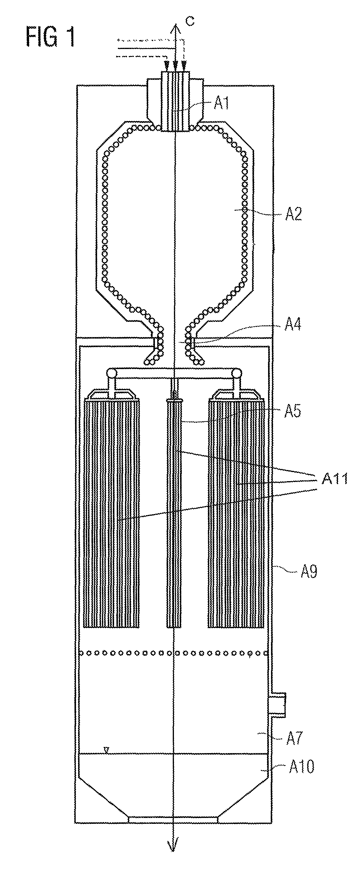
[0028]The basic process concept according to the invention is explained with reference to FIG. 1.

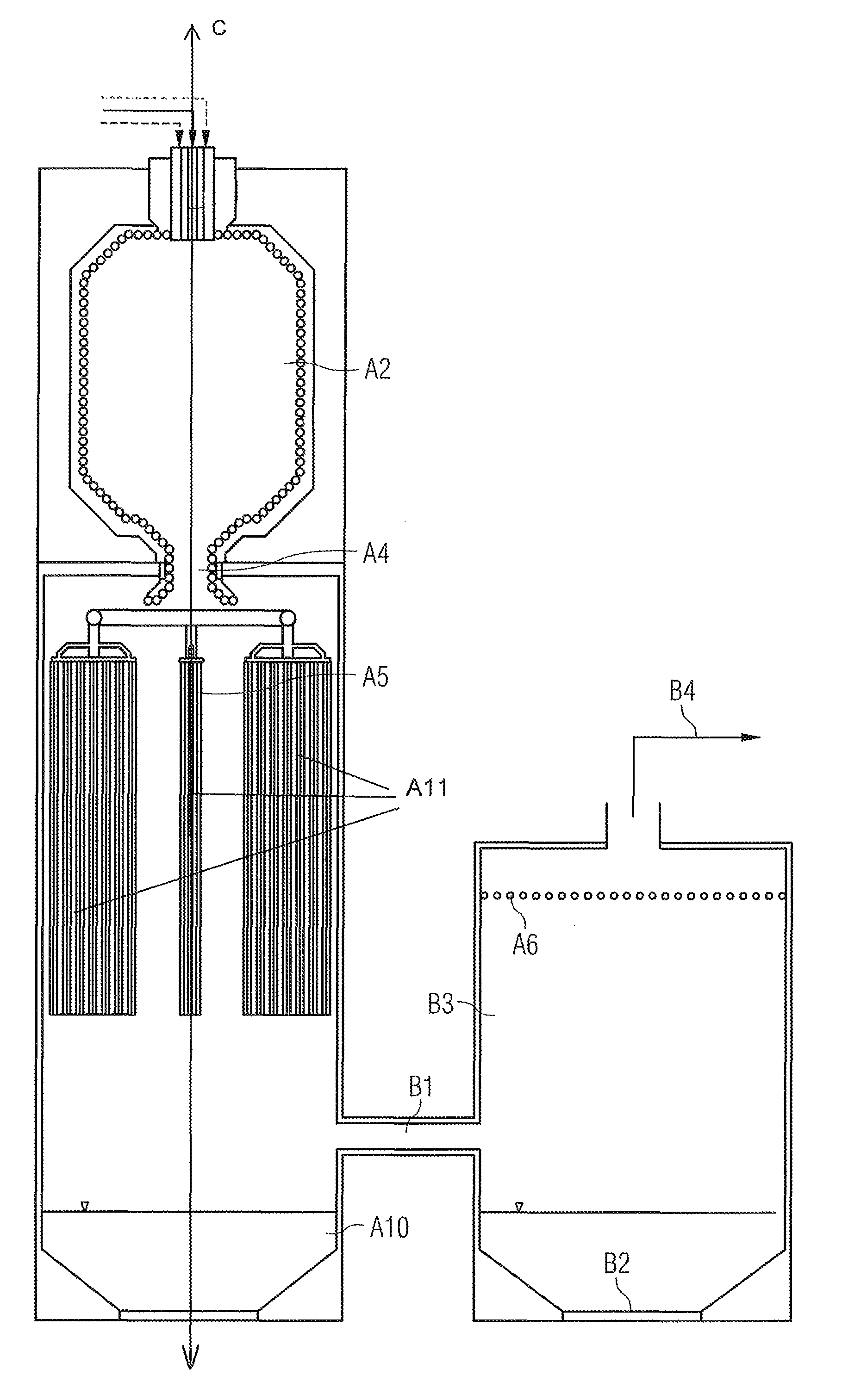
[0029]The arrangement according to the invention comprises three main components:[0030]the gasification reactor (A2)[0031]the waste heat unit (A5)[0032]the full quench system (A7)

[0033]The conversion of the ash-containing feedstock is performed in the gasification reactor (A2) in a flame reaction at temperatures above the ash fusion temperature. The hot raw gas and the molten slag flow out of the gasification reactor (A2) through the slag removal body (A4) into the waste heat unit (A5). The waste heat unit can be a radiation cooler. The radiation cooler is formed with a plurality of surface-area modules (A11), which are arranged with their narrow side at a prespecified distance from the central axis (C) of the entrained flow gasifier and with th...


PUM

PropertyMeasurementUnit
temperaturesaaaaaaaaaa
temperatureaaaaaaaaaa

Abstract

An entrained flow gasifier designed as a component for an Integrated Gasification Combined Cycle plant of optimized efficiency is provided. The raw gas initially flows through a waste heat unit designed as a radiation cooler and subsequently flows through a full water quench. This results in a higher ratio of steam in the raw gas, which decreases the medium-pressure steam supply before the water-gas shift and thus improves efficiency in IGCC plants with CO2 separation.

Description

CROSS REFERENCE TO RELATED APPLICATIONS[0001]This application is the US National Stage of International Application No. PCT / EP2010 / 059204, filed Jun. 29, 2010 and claims the benefit thereof. The International Application claims the benefits of German application No. 10 2009 035 300.3 DE filed Jul. 30, 2009. All of the applications are incorporated by reference herein in their entirety.FIELD OF INVENTION[0002]The invention relates to an apparatus for using the sensible heat from raw gas generated in an entrained flow gasifier, in particular from the gasification of ash-forming fuels.BACKGROUND OF INVENTION[0003]In future, new requirements will be placed on fossil-fuel power plants, such as, for example, minimum emissions and additional CO2 separation. Currently, the most advanced power plant concept for CO2 separation is the Integrated Gasification Combined Cycle (IGCC). This technology encompasses gasification of the fuel before the actual combined cycle power plant (CCGT). Since CO...

Claims


Application Information

Patent Timeline
Patent Type & Authority Patents(United States)
IPC IPC(8): B01J7/00C10J3/84C10J3/52C10K1/10C10J3/76C10J3/78C10J3/82C10K1/08C10J3/48
CPCC10J3/526C10J3/485C10J3/76C10J3/78C10J3/82C10J3/84C10K1/08C10K1/10C10K1/101C10J2200/09C10J2300/1884C10J2300/1892Y02E20/16Y02E20/18Y02P20/129
Inventor FLEISCHER, THOMASHANNEMANN, FRANKREUTHER, CHRISTIANSCHINGNITZ, MANFREDSCHUMANN, RALPH
Owner SIEMENS ENERGY GLOBAL GMBH & CO KG
Why Eureka
Try Eureka