Method for geo-referencing an imaged area

a geo-referencing and image technology, applied in image enhancement, reradiation, instruments, etc., can solve the problems of large distance with decametric efficiency, error of approximately 270 m, and error that is found

Active Publication Date: 2015-11-24
THALES SA
View PDF24 Cites 4 Cited by
  • Summary
  • Abstract
  • Description
  • Claims
  • Application Information

AI Technical Summary

Benefits of technology

[0057]discretely, because it is possible to geo-locate an object which has not been directly illuminated by the range finder, which avoids having to perform an active measurement on a sensitive object to be located, and thus represents an advantage for tactical operations that require a level of discretion.

Problems solved by technology

These errors may be aggregated to ultimately introduce an error of approximately 270 m for the positioning of the point P.
Such errors are found nevertheless also in low-altitude terrestrial optronics systems (helicopters, mini UAVs) which are fixed, for example, at the top of a vehicle mast or a ship's mast.
However, most of these systems have to acquire and characterize the positioning of objects moving at great distance with decametric efficiency.
However, these landmarks, generally taken from exposures close to the vertical, are difficult to pair with the strongly oblique image automatically, and are subject to the aging of the information.
One of the difficulties is to acquire this performance rapidly and at any point of the globe without having to use true world coverage information, which is difficult to pair with the image straight away, but not subject to the aging of the information.
The systems used do not generally offer any associated imaging and, when they do have it, the two systems are not coupled.
The need for an operator in the loop to control the quality of assembly of the images and of the geo-referencing of an area covered by a number of images is unfeasible in the conditions of use of applications notably requiring a much shorter implementation time, close to real time.
For the terrestrial applications, the displacement of the detector is not always possible and its size is sometimes limited with regard to the areas to be acquired.
The coverage of large areas by an aeroterrestrial means is more difficult since:in airborne cueing, the trajectory is ensured by a maneuvering platform,in terrestrial cueing, the platform is fixed or has little mobility.
However, the difficulty associated with finely knowing the pointing over time (between the directions of the image corresponding to the direction of the array) degrades the internal consistency of the image (which allows for control of its geometry) and therefore one of the strong characteristics of optronics.

Method used


Image

  • Method for geo-referencing an imaged area
  • Method for geo-referencing an imaged area
  • Method for geo-referencing an imaged area

Examples


first embodiment

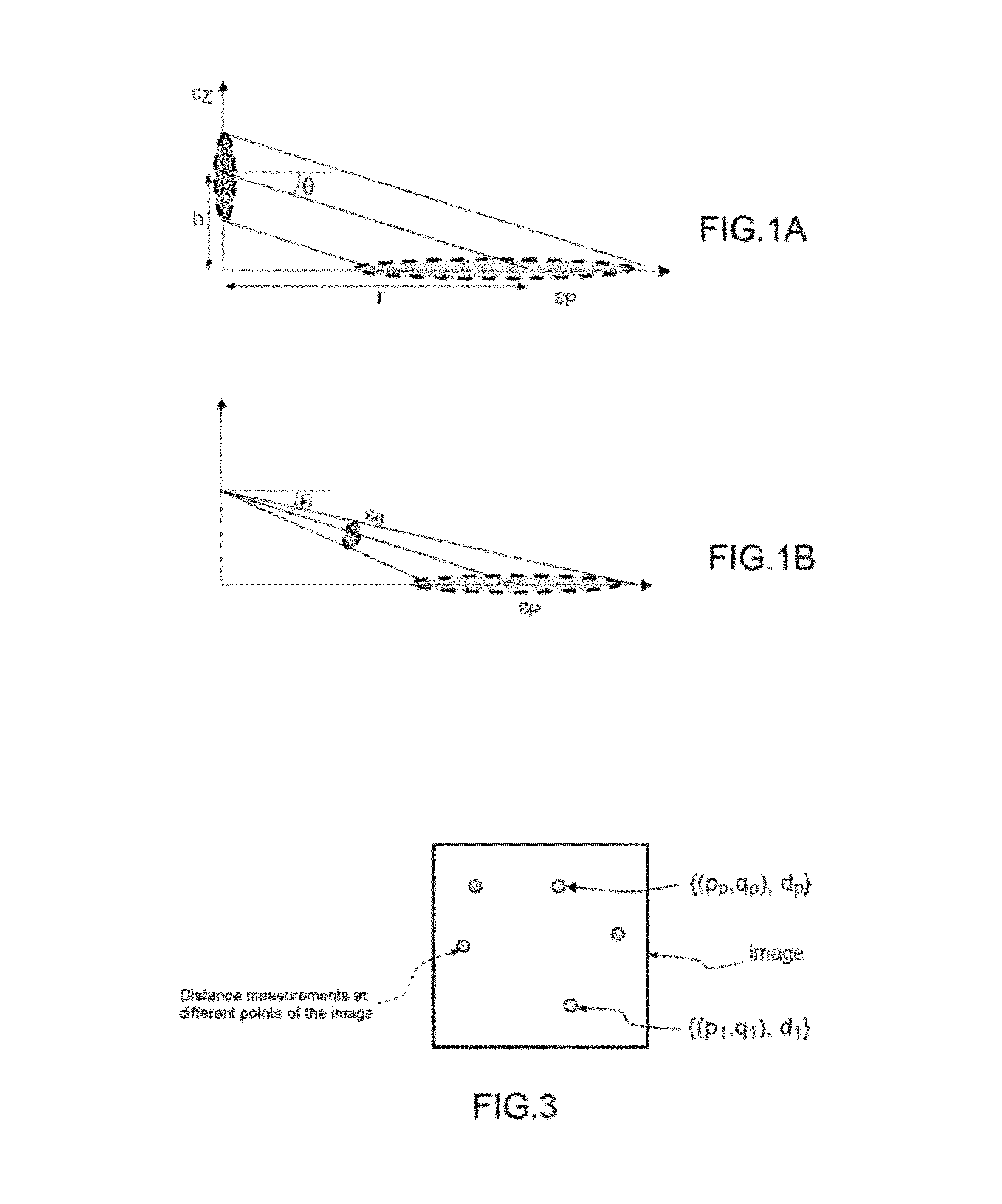
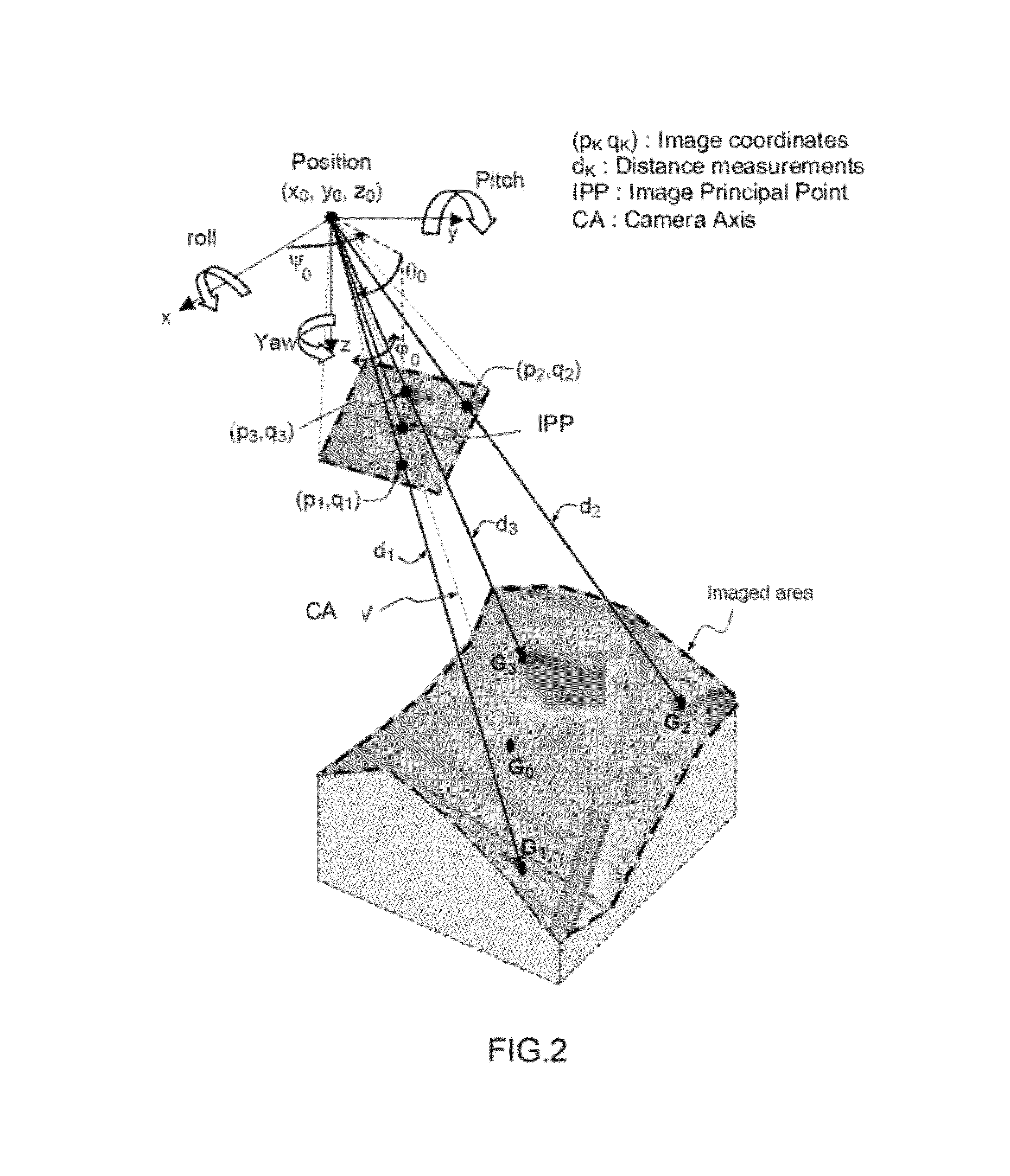
[0263]According to the method, described in relation to FIGS. 2 and 3, a single image is acquired and P points are range-found in this image (M=K=1 in the two figures, P=3 in FIG. 2 and P=5 in FIG. 3). This makes it possible to perform the geo-referencing of the imaged area almost instantaneously with the acquisition of an adjustable number of distances by the range finder.

[0264]As illustrated in FIG. 4, to obtain these P distances in one and the same image, the range finder is, for example, equipped with means for splitting the beam emitted into P separate beams, each separate beam targeting a point to be range-found; in this case, the energy Ep of a separate beam is less than Et / P, Et being the total energy of the beam before it is split.

[0265]According to one alternative, the range finder is equipped with rapid beam-deflection means, this deflection being such that the time to acquire each distance is less than or equal to the ratio of the time to acquire this image to the number...

second embodiment

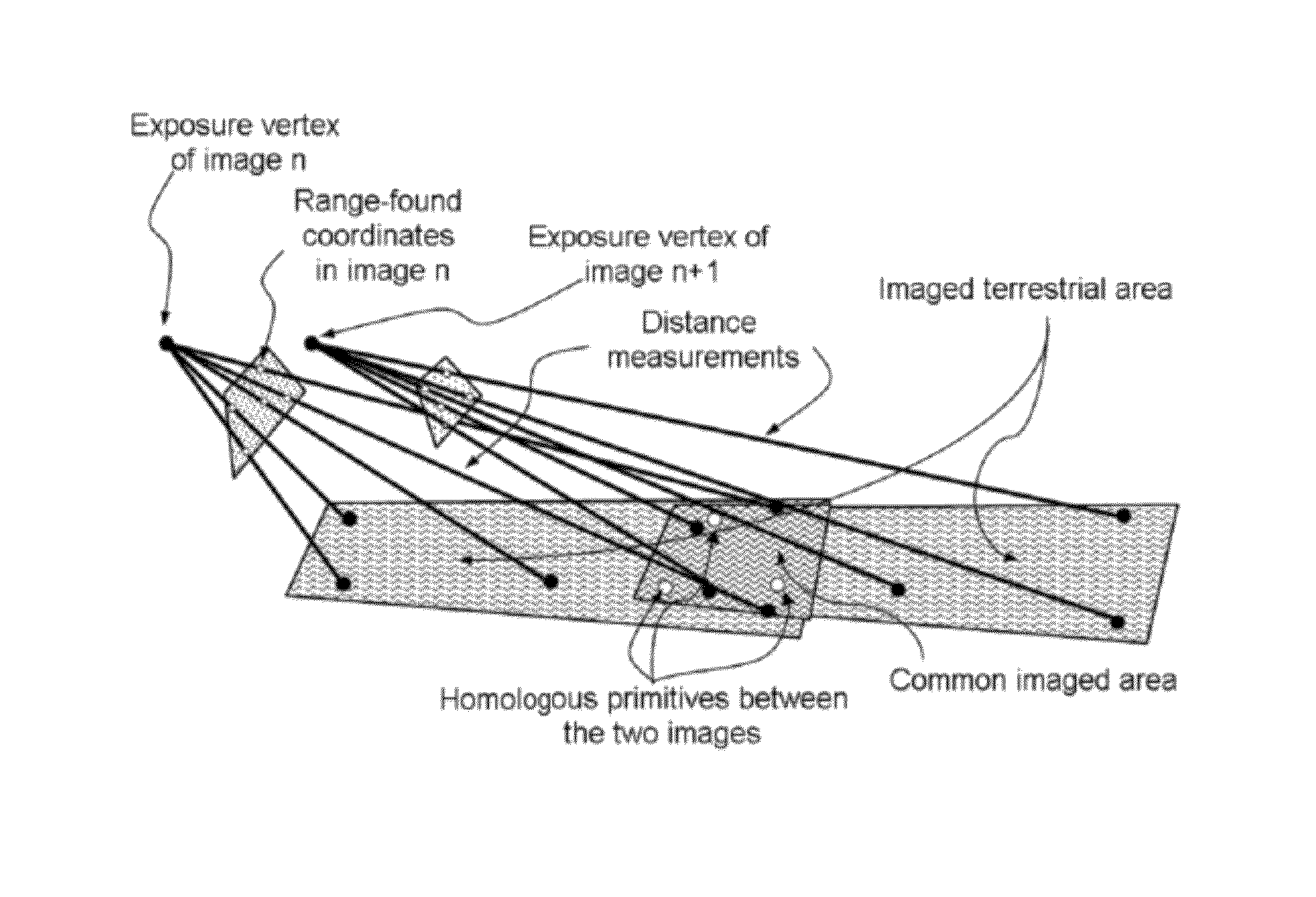
[0270]According to the method, described in relation to FIGS. 5 and 6, M images are acquired in succession (with M>1) and P points are range-found in K images, with 1≦K≦M. This in a way is the same as the preceding embodiment, but extended to M images.

[0271]It will be noted that it is possible to form one large image from M images, but this is not essential in estimating the parameters xe, ye, ze, φe, θe, ψe of each image.

[0272]When there is more than one image, it is essential for the images to overlap at least two by two in order for them to be able to be mapped together. The overlap may vary within a wide range from a minimum of the order of 10% to almost 100% (a value of 60% corresponds to the conventional aero-triangulation conditions for the civilian applications in which the acquisitions are vertical). Two successive images are mapped together by using homologous primitives (representing the same details of the scene) belonging to the overlaps of the images. These primitives ...

third embodiment

[0290]According to the method, described in relation to FIGS. 7A and 7B and which is a particular case of the preceding embodiment, M images are acquired and P points are range-found in K images with K=P; there is therefore a single range-found point in each of the K images (M=4, K=P=3 in the figures). Since the range finder is harmonized with the COA of the detector, these range-found points are respectively at the center of each of the K images. As can be seen in FIG. 7B, 2 homologous points are extracted in the area of overlap between the images 1 and 2, three are extracted in the area of overlap between the images 2 and 3, and two are extracted in the area of overlap between the images 3 and 4. This approach does not require any material change to the existing equipment or equipment that is now envisaged.

[0291]It will also be noted that it is possible to have P>K. Some images may not have any range-found point, since they have homologous primitives with other images which themse...


PUM


Abstract

A method for geo-referencing an area by an imaging optronics system which comprises acquiring M successive images by a detector, the imaged area being distributed between these M images, with M≧1. It comprises: measuring P distances d1, d2, . . . , dP between the system and P points of the area, called range-found points, with P≧3, distributed in K of said images with 1≦K≦M; acquiring the positioning xm, ym, zm of the detector at acquisition of the M images; measuring the attitude φm, θm, ψm of the detector at acquisition of the M images; acquiring the coordinates in these K images of image points (p1, q1), (p2, q2), . . . , (pP, qP) corresponding to the P range-found points; and estimating the parameters of exposure conditions xe, ye, ze, ψe, θe, φe corresponding to the M images as a function of positionings, of attitudes, distances and coordinates of the image points, to correct errors on the parameters xm, ym, zm, ψm, θm, φm of each of the M images.

Description

CROSS-REFERENCE TO RELATED APPLICATIONS[0001]This application is a National Stage of International patent application PCT / EP2010 / 069697, filed on Dec. 15, 2010, which claims priority to foreign French patent application No. FR 0906095, filed on Dec. 16, 2009, the disclosures of which are incorporated by reference in their entirety.FIELD OF THE INVENTION[0002]The present invention refers to the geo-referencing of an area by means of an optronics system, with a decametric performance class, and more particularly in strongly oblique exposure conditions.BACKGROUND[0003]FIG. 1 illustrate the positioning (or geo-locating) errors for a point P of an area, induced by measurement uncertainties in strongly oblique exposure conditions encountered, for example, in aero-terrestrial applications in which the optronics system is situated close to the ground compared to the distance to the object (airborne, the ratio of the distance to the object to flight altitude is in the order of 5—and even mor...

Claims


Application Information

Patent Timeline
Patent Type & Authority Patents(United States)
IPC IPC(8): G06K9/32G06K9/00G06T17/05G06T7/00G01C11/34G01S17/89G01C11/06
CPCG01S17/89G01C11/06G01C11/34G06T7/0028G06T7/0042G06T17/05G06T2207/10032G06T7/33G06T7/73
Inventor SIMON, ALAIN
Owner THALES SA
Why Eureka
Try Eureka