Self-orienting syringe and syringe interface

Active Publication Date: 2015-12-01
BAYER HEALTHCARE LLC
View PDF216 Cites 132 Cited by
  • Summary
  • Abstract
  • Description
  • Claims
  • Application Information

AI Technical Summary

Benefits of technology

[0009]In view of certain disadvantages of the existing connection interfaces between the syringe and the fluid injector, there is a need in the art for an improved syringe and connection interface between the syringe and the fluid injector that overcomes the deficiencies of the prior art. There is an addit

Problems solved by technology

Such syringe injector features require additional time and effort to load/remove the sy

Method used


Image

  • Self-orienting syringe and syringe interface
  • Self-orienting syringe and syringe interface
  • Self-orienting syringe and syringe interface

Examples


Embodiment Construction

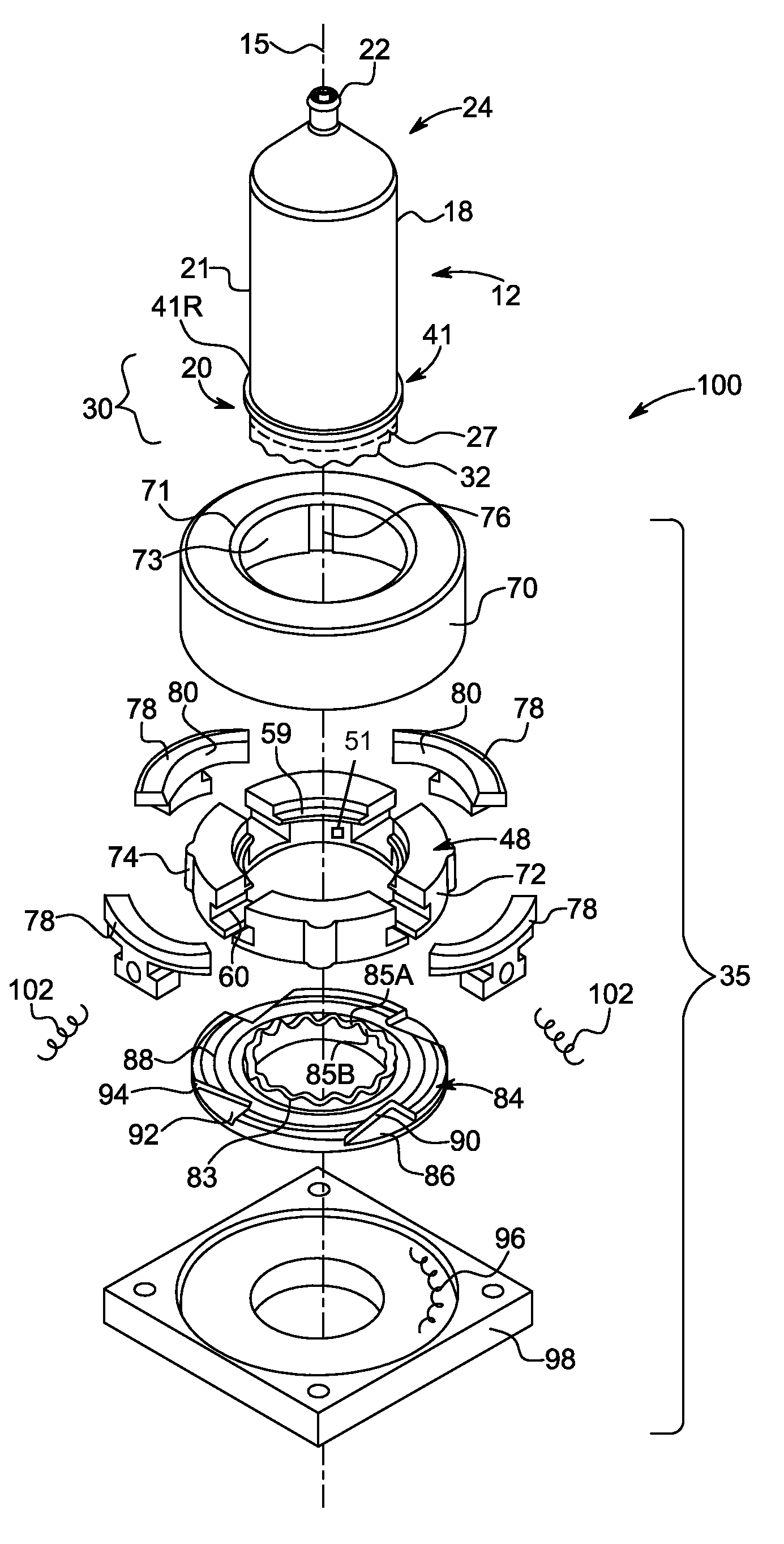
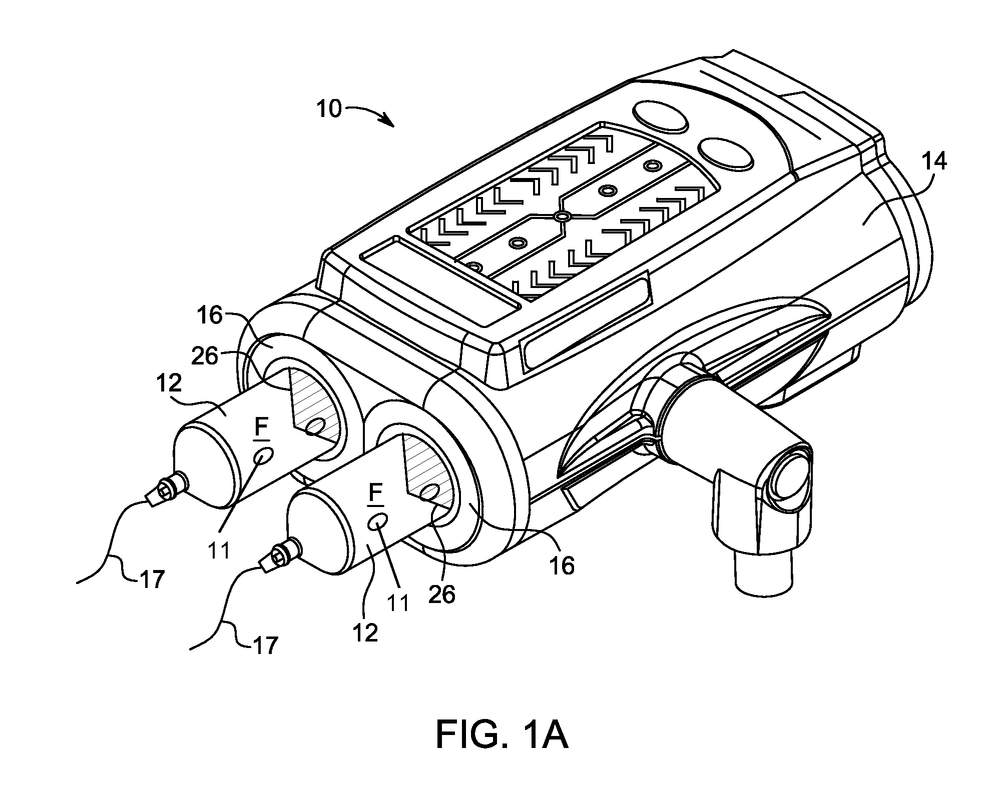
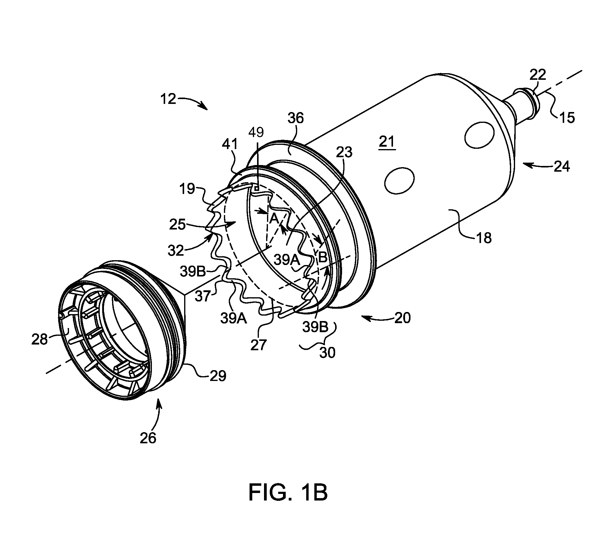
[0034]For purposes of the description hereinafter, the terms “upper”, “lower”, “right”, “left”, “vertical”, “horizontal”, “top”, “bottom”, “lateral”, “longitudinal”, and derivatives thereof shall relate to the disclosure as it is oriented in the drawing figures. When used in relation to a syringe, the term “proximal” refers to a portion of a syringe nearest to an injector when a syringe is oriented for connecting to an injector. The term “distal” refers to a portion of a syringe farthest away from an injector when a syringe is oriented for connecting to an injector. The term “radial” refers to a direction in a cross-sectional plane normal to a longitudinal axis of a syringe extending between proximal and distal ends. The term “circumferential” refers to a direction around an inner or outer surface of a sidewall of a syringe. The term “axial” refers to a direction along a longitudinal axis of a syringe extending between proximal and distal ends. The term “self-orienting” means that a...


PUM


Abstract

A syringe includes a barrel having a distal end, a proximal end, and a sidewall extending therebetween along a longitudinal axis. At least one engagement member protrudes from a terminal portion of the sidewall in a proximal direction along the longitudinal axis. The at least one engagement member tapers axially in a direction from the distal end toward the proximal end. The at least one engagement member is configured for engagement with a locking mechanism of a fluid injector to releasably lock the syringe with the fluid injector. A taper of the at least one engagement member is configured to rotationally guide the syringe into alignment with the locking mechanism and axially eject the syringe upon rotation of the syringe. The locking mechanism operatively engages the at least one engagement member regardless of an orientation of the syringe about the longitudinal axis relative to the injector.

Description

BACKGROUND OF THE DISCLOSURE[0001]1. Field of the Disclosure[0002]The present disclosure relates generally to a system including a self-orienting, front-loading syringe for use with a fluid injector and, further, to a connection interface for securing the syringe to the fluid injector and to a method for loading and removal of the syringe to and from the fluid injector.[0003]2. Description of Related Art[0004]In many medical diagnostic and therapeutic procedures, a medical practitioner, such as a physician, injects a patient with one or more medical fluids. In recent years, a number of injector-actuated syringes and fluid injectors for pressurized injection of medical fluids, such as a contrast solution (often referred to simply as “contrast”), a flushing agent, such as saline, and other medical fluids have been developed for use in procedures such as angiography, computed tomography (CT), ultrasound, magnetic resonance imaging (MRI), positron emission tomography (PET), and other mo...

Claims


Application Information

Patent Timeline
IPC IPC(8): A61M37/00A61M5/145
CPCA61M5/14546A61M5/14566A61M2005/14573A61M2205/6063A61M5/1408A61M5/007A61M5/31545A61M2005/14553A61M2205/19A61M5/145
Inventor COWAN, KEVIN PTUCKER, BARRY LUBER, III, ARTHUR ERHINEHART, EDWARD JSPOHN, MICHAEL A
Owner BAYER HEALTHCARE LLC
Why Eureka
Try Eureka