Heat pump apparatus with ejector cycle

a technology of ejector cycle and heat pump, which is applied in the direction of lighting and heating apparatus, refrigeration machines, compression machines with reversible cycles, etc., can solve the problems of inhibiting efficiency degradation, etc., and achieve high efficiency operation, high capacity, and high efficiency operation.

Active Publication Date: 2015-12-01
MITSUBISHI ELECTRIC CORP
View PDF23 Cites 7 Cited by
  • Summary
  • Abstract
  • Description
  • Claims
  • Application Information

AI Technical Summary

Benefits of technology

[0012]The heat pump apparatus according to the present invention includes a main refrigerant circuit that utilizes an ejector, and two sub-refrigerant circuits that bypass the ejector. It is possible to perform switching between the high efficiency operation and the high capacity operation by, according to the state of the load, switching the circuit through which the refrigerant flows. Moreover, since the branching positions of the main refrigerant circuit and the two sub-refrigerant circuits, the installation position of the third heat exchanger, and the like are optimized, both the high efficient operation and the high capacity operation can be operated efficiently.

Problems solved by technology

Thereby, it is possible to inhibit the efficiency degradation due to shortage of the amount of refrigerant circulated to the evaporator caused by shortage of driving force of the ejector.

Method used


Image

  • Heat pump apparatus with ejector cycle
  • Heat pump apparatus with ejector cycle
  • Heat pump apparatus with ejector cycle

Examples


embodiment 1

[0025]First, the structure of a heat pump apparatus 100 according to Embodiment 1 will be explained.

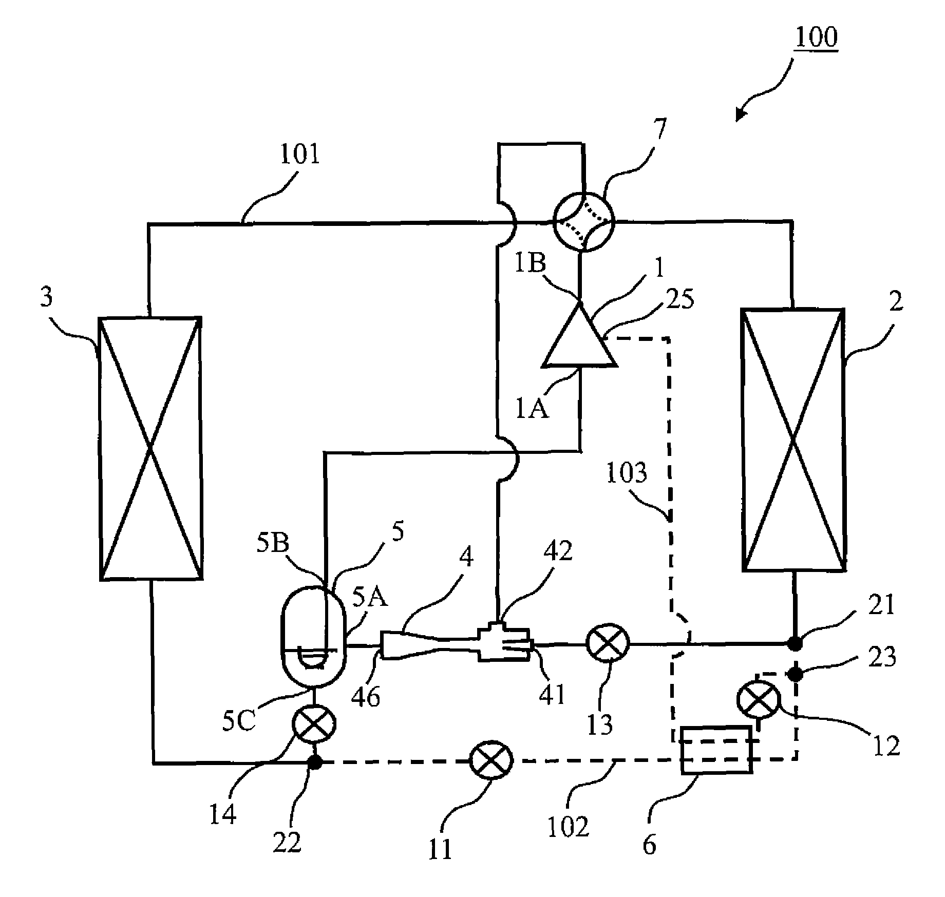
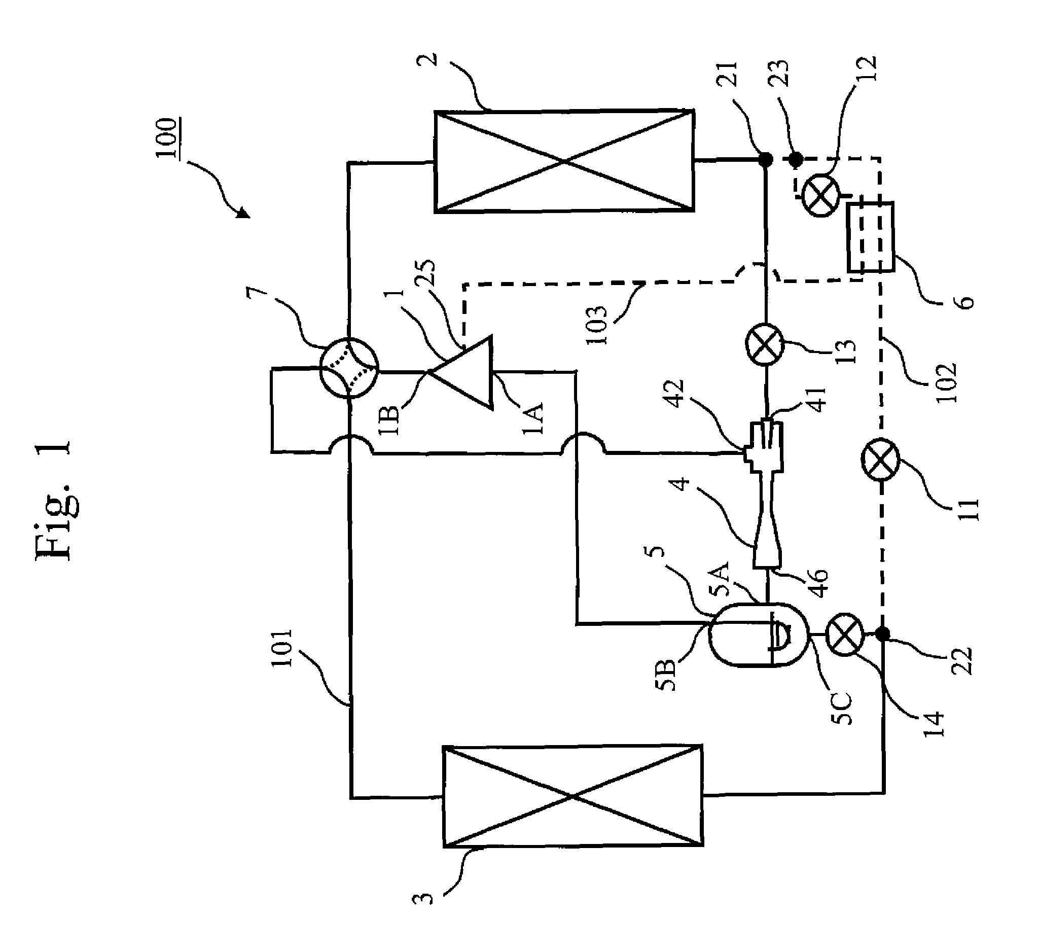
[0026]FIG. 1 shows a block diagram of the heat pump apparatus 100 according to Embodiment 1.

[0027]As shown in FIG. 1, the heat pump apparatus 100 includes a main refrigerant circuit 101 represented by a solid line, and sub-refrigerant circuits 102 and 103 represented by dashed lines.

[0028]In the main refrigerant circuit 101, a discharge port 1B of a compressor 1 and a heat exchanger 2 (first heat exchanger) are connected by piping through a four-way valve 7. The heat exchanger 2 and a first inlet 41 of an ejector 4 are connected by piping. An outlet 46 of the ejector 4 and an inlet 5A of a gas-liquid separator 5 are connected by piping. A gas side outlet 5B of the gas-liquid separator 5 and a suction port 1A of the compressor 1 are connected by piping. A liquid side outlet 5C of the gas-liquid separator 5 and a heat exchanger 3 (second heat exchanger) are connected by piping. The heat...

embodiment 2

[0110]The heat pump apparatus 100 according to Embodiment 1 performs an ejector aided operation when the outdoor temperature is higher than or equal to 2° C. and lower than 7° C., and performs an injection operation without using the ejector 4 when the outdoor temperature is lower than 2° C. That is, in Embodiment 1, the operation utilizing the ejector 4 and the injection operation are alternatively switched according to the outdoor temperature.

[0111]The heat pump apparatus 100 according to Embodiment 2 newly sets up a reference temperature B ° C., which is lower than 2° C., as the outdoor temperature. When the outdoor temperature is higher than or equal to B ° C. and lower than 2° C., the heat pump apparatus 100 performs a compound operation which utilizes the ejector 4 and makes the refrigerant flow also to the second sub-refrigerant circuit 103. Moreover, the heat pump apparatus 100 performs an injection operation using no ejector 4 when the outdoor temperature is lower than B ° ...


PUM


Abstract

In a heat pump apparatus, switching between high efficiency operation, and high capacity operation, is performed according to the state of the load. A main refrigerant circuit uses an ejector. A first sub-refrigerant circuit connects a portion between a heat exchanger and an ejector to a portion between a gas-liquid separator and a heat exchanger A second sub-refrigerant circuit connects a portion between the heat exchanger and the ejector to an injection pipe of a compressor. When the load is medium, refrigerant is circulated in the main refrigerant circuit to perform an efficient ejector aided operation. When the load is large, a high capacity injection operation is performed by flowing refrigerant to the second sub-refrigerant circuit. When the load is small, a simple bypass operation prevents degradation of efficiency by flowing refrigerant to the first sub-refrigerant circuit.

Description

TECHNICAL FIELD[0001]The present invention relates to a heat pump apparatus equipped with an ejector, for example.BACKGROUND ART[0002]In Patent Literature 1, there is disclosed an air conditioning apparatus that performs switching, depending on the situation, between a power recovery operation utilizing an ejector and a decompression operation using a general expansion valve, without using the ejector.[0003]In this air conditioning apparatus, the operation is switched from the power recovery operation to the decompression operation when pressure decreases at the high pressure side. Thereby, it is possible to inhibit the efficiency degradation due to shortage of the amount of refrigerant circulated to the evaporator caused by shortage of driving force of the ejector.CITATION LISTPatent Literature[0004]Patent Literature 1: Japanese Unexamined Patent Publication No. 2008-116124SUMMARY OF INVENTIONTechnical Problem[0005]In the air conditioning apparatus disclosed in the Patent Literatur...

Claims


Application Information

Patent Timeline
Patent Type & Authority Patents(United States)
IPC IPC(8): F25B41/04F25B13/00F25B41/00
CPCF25B13/00F25B41/00F25B2400/23F25B2400/0407F25B2400/13F25B2341/0011
Inventor OKAZAKI, TAKASHINOMOTO, SOHIGASHIIUE, SHINYAMINAMISAKO, HIROKAZU
Owner MITSUBISHI ELECTRIC CORP
Why Eureka
Try Eureka