Ultrasound detecting system and method and apparatus for automatically controlling freeze thereof

a technology of ultrasonic detection and freeze, applied in the field of ultrasonic detection system, can solve the problems of inaccurate auto-freezing technique, inability to realize energy savings during this waiting period, and inability to automatically control freez

Active Publication Date: 2015-12-08
GE MEDICAL SYST GLOBAL TECH CO LLC
View PDF17 Cites 3 Cited by
  • Summary
  • Abstract
  • Description
  • Claims
  • Application Information

AI Technical Summary

Benefits of technology

[0026]During the period when a probe is in a frozen state: if sensor 2 detects that a user is approaching a device main body, a control unit operates so as to activate an ultrasound detecting system, and waits for detecting results of sensor 1, instead of unfreezing the probe immediately; if sensor 1 detects that the user or the user's body parts are approaching the probe, the control unit activates the ultrasound detecting system and unfreezes the probe. In an embodiment, if sensor 1 detects that the user or the user's body parts are approaching the probe during the freeze period of the probe, the control unit activates the ultrasound detecting system and freezes the probe, regardless of detecting results of sensor 2. In another embodiment, release of the frozen state of the probe must be realized manually by the user, for example, by pressing a certain button or switch on the ultrasound detecting system or implementing other operations on the ultrasound detecting system.
[0023]Sensors 1 and 2 send their respective detecting results to a control unit of an ultrasound detecting system (not shown), and then the control unit performs operation of freeze controlling on the ultrasound detecting system based on the detecting results of sensors 1 and 2. In an embodiment of the invention, the control unit puts the probe in a frozen state when sensor 1 detects that the probe is not operated, without necessarily waiting a certain period, thereby reducing energy consumption. In such an embodiment, in fact another sensor 2 can be omitted.

Problems solved by technology

However, no energy savings can be realized during this waiting period.
Moreover, this technique of auto-freeze is not accurate.
Thus, when the time for no operation on a user interface exceeds the prescribed value, the scan of a probe will be mistakenly frozen.

Method used


Image

  • Ultrasound detecting system and method and apparatus for automatically controlling freeze thereof
  • Ultrasound detecting system and method and apparatus for automatically controlling freeze thereof
  • Ultrasound detecting system and method and apparatus for automatically controlling freeze thereof

Examples


Embodiment Construction

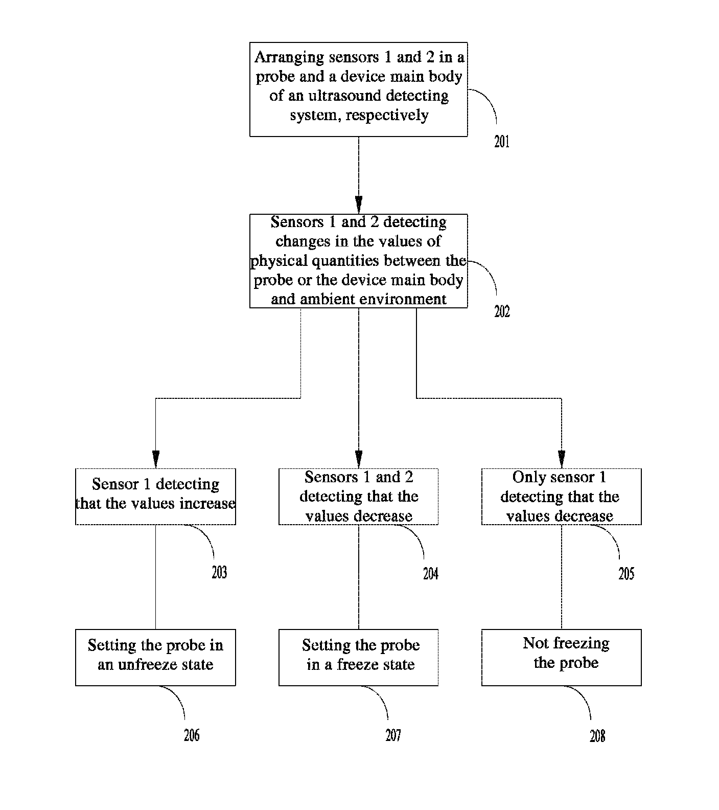
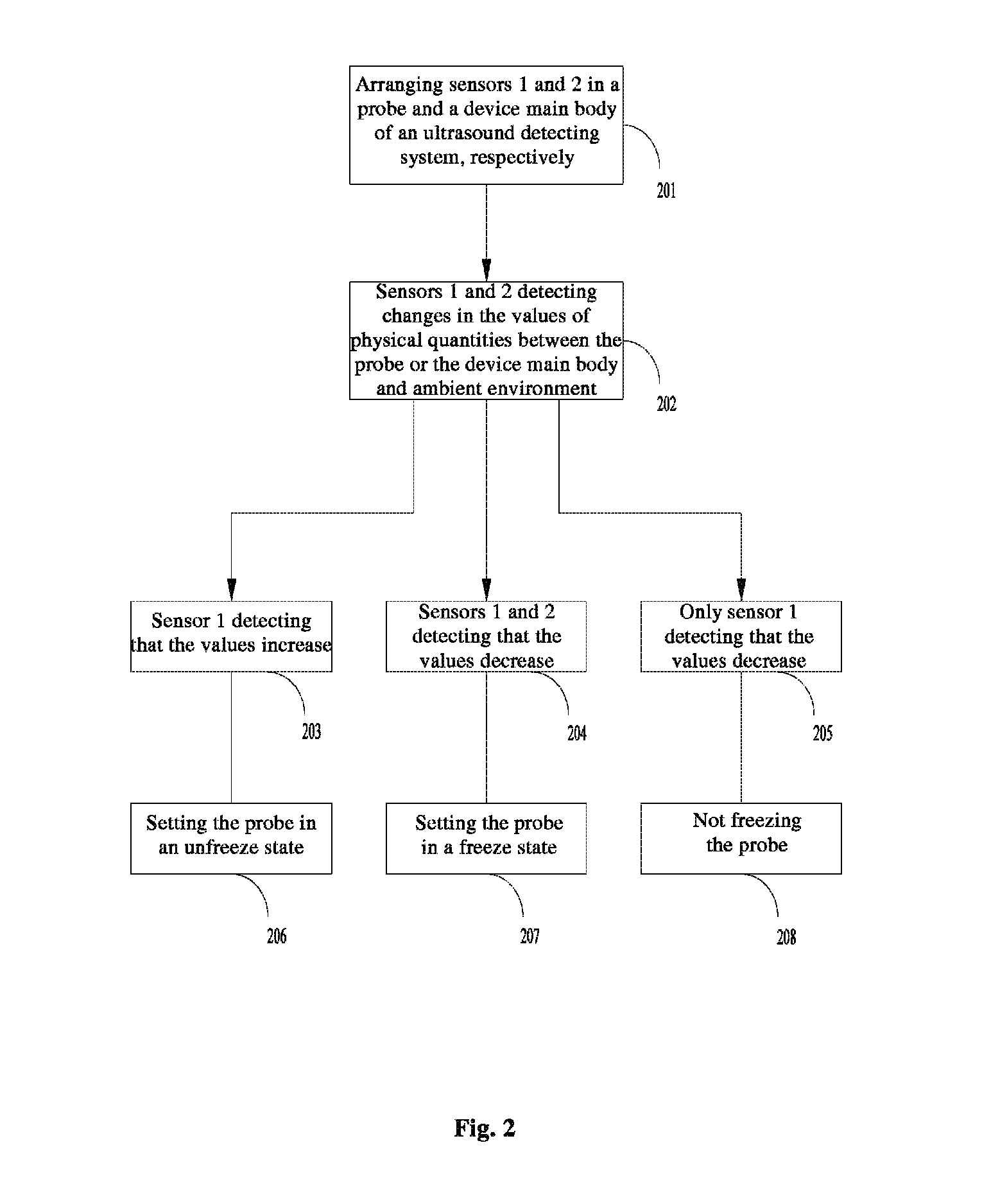
[0010]Specific embodiments of the invention will be described in detail below, but the invention is not limited to the following specific embodiments.

[0011]Embodiments of the present invention use a proximity sensor that is installed in a probe and / or an ultrasound detecting system to detect whether a user is operating the probe or approaching the ultrasound detecting system. The proximity sensor is a sensor that is used to detect a difference in capacitance, inductance or other physical quantities between non-contact conditions and proximity conditions. More particularly, capacitive sensors are becoming more and more popular in the field of touch panels, and a touch panel of a notebook is generally designed based on this technique.

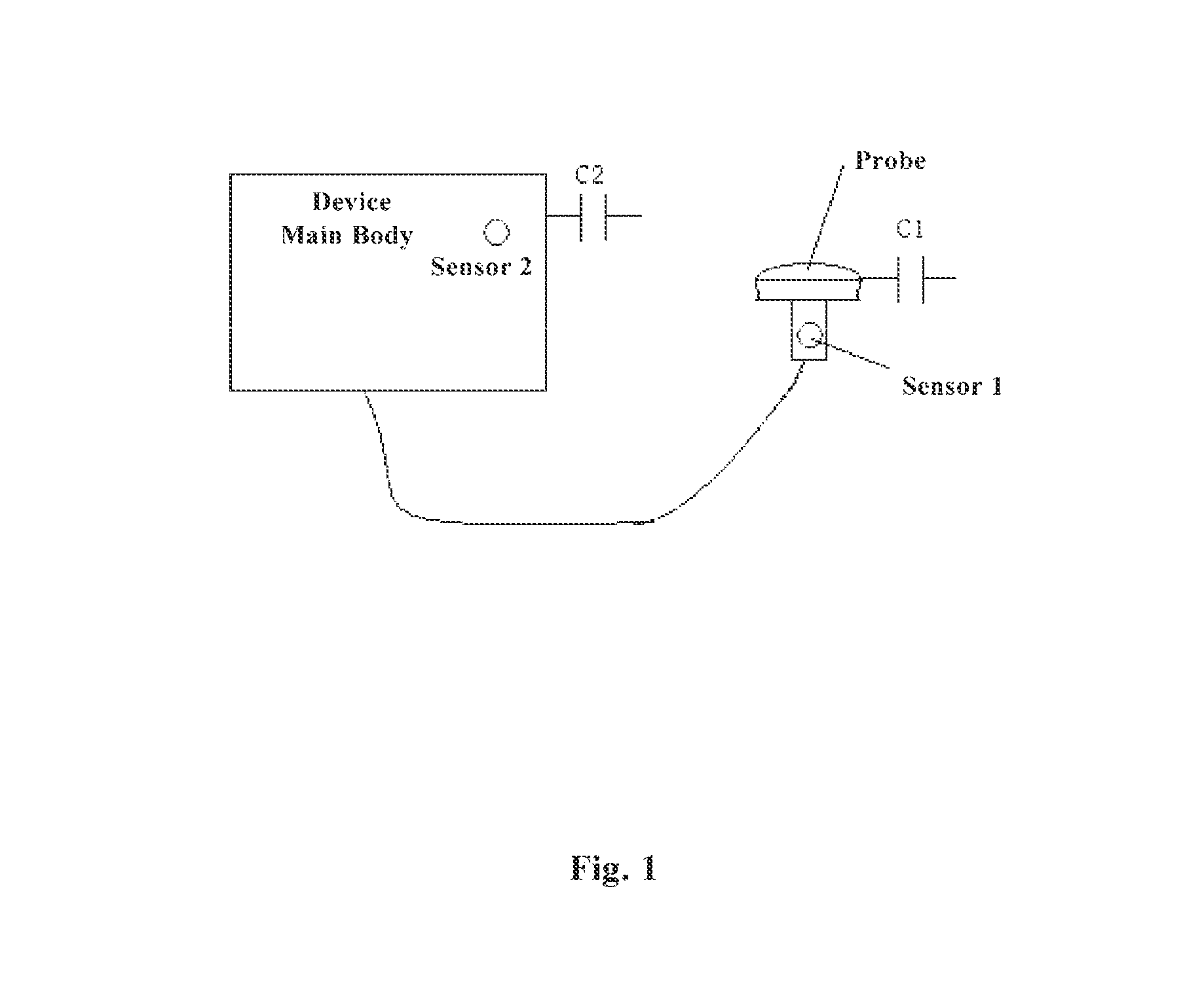
[0012]FIG. 1 schematically shows a composition of an ultrasound detecting system according to an embodiment of the invention. The ultrasound detecting system comprises two parts: a device main body and an ultrasound probe, wherein the ultrasound is connec...


PUM


Abstract

An apparatus for automatically controlling a state of operation of an ultrasound detecting system is provided. The apparatus comprises a first sensor disposed in a probe of the ultrasound detecting system and connected to a device main body, wherein the first sensor is configured to detect if the probe is being operated, and a control unit configured to control the state of operation of the ultrasound detecting system based on the detecting results of the first sensor.

Description

BACKGROUND OF THE INVENTION[0001]Embodiments of the present invention generally relate to an ultrasound detecting system, and more particularly, relate to an ultrasound detecting system and method and apparatus for automatically controlling freeze thereof.[0002]For energy saving, some ultrasound detecting systems normally have an auto-freeze function. This function will enable an ultrasound system to freeze the scan of an ultrasound probe automatically after a certain period of no operation on a user interface, so as to save energy and extend the life of the probe. This period to be waited before performing freeze is defined through experience. However, no energy savings can be realized during this waiting period.[0003]Moreover, this technique of auto-freeze is not accurate. For example, when a user stops operation on the user interface, he / she is actually conducting other operations so as to obtain a better image. Thus, when the time for no operation on a user interface exceeds the...

Claims


Application Information

Patent Timeline
Patent Type & Authority Patents(United States)
IPC IPC(8): G01S15/02A61B8/00G01S7/52A61B8/08
CPCA61B8/4254A61B8/4263A61B8/4433A61B8/54G01S7/52096A61B8/08
Inventor JI, KAIXUE, LINHAI
Owner GE MEDICAL SYST GLOBAL TECH CO LLC
Why Eureka
Try Eureka