Process for bonding arrays of ceramic filters

a technology of ceramic filters and arrays, which is applied in the direction of ceramicware, separation processes, machines/engines, etc., can solve the problems of filter cracking, and inadequate adhesion and mechanical failure of honeycombs

Inactive Publication Date: 2015-12-08
DOW GLOBAL TECH LLC
View PDF32 Cites 0 Cited by
  • Summary
  • Abstract
  • Description
  • Claims
  • Application Information

AI Technical Summary

Benefits of technology

[0008]The methods of the invention allow consistent application of adhesive layers within specific thickness and thickness variation limits. The methods do not require the use of assembly apparatus with special spacers built-in, avoid leaving spacers or the residue of spacers in the assembled arrays. The methods allow adjusting the thickness of the cement layer from array to array or run of arrays to arrays. The system allows for the use of different thicknesses of cement in the same array while staying within specified cement layer variance limits.

Problems solved by technology

Diesel engines, because of the way they operate, emit soot particles or very fine droplets of condensate or a conglomerate of the two (particulates) as well a typical harmful gasoline engine exhausts (i.e., HC and CO).
This burning of soot results in stresses from axial and radial temperature differences that can cause cracking of the filter.
If they are too thin, there may be inadequate adhesion and mechanical failure during use of the honeycombs.
If they are too thick, there may be excessive thermal gradients during heating and cooling of the honeycomb which can also result in mechanical failure of the honeycombs.
Further if the seams are too thick the honeycomb may exhibit high back pressures, which can negatively impact the performance of the honeycombs and the systems utilizing the honeycombs.
Such processes require special assembly steps, burn out steps or leave spacers and / or the residue of the spacers in the seams which can reduce the effectiveness of the resulting ceramic filters.

Method used


Image

  • Process for bonding arrays of ceramic filters
  • Process for bonding arrays of ceramic filters
  • Process for bonding arrays of ceramic filters

Examples


Embodiment Construction

[0010]The disclosures of all articles and references, including patent applications and publications, are incorporated by reference for all purposes. The following claims are hereby incorporated by reference into this written description. This application claims priority from U.S. Provisional Ser. No. 61 / 665,362 filed Jun. 28, 2012, incorporated herein by reference in its entirety. One or more as used herein means that at least one, or more than one, of the recited components may be used as disclosed.

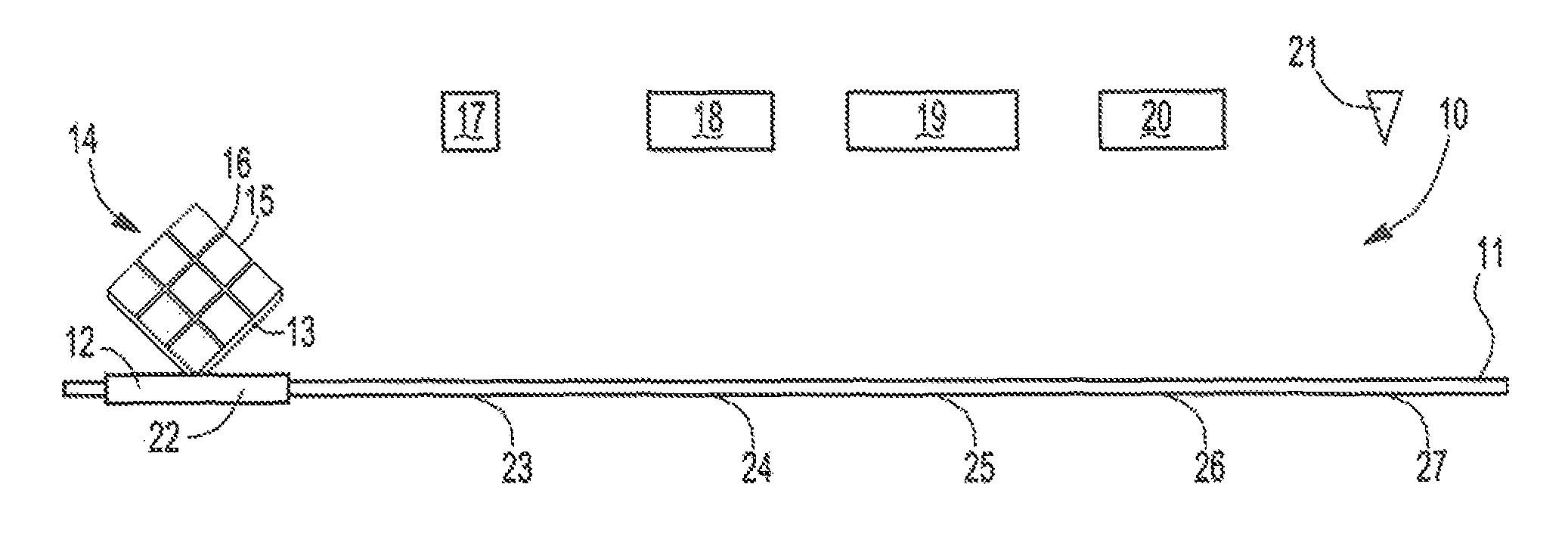
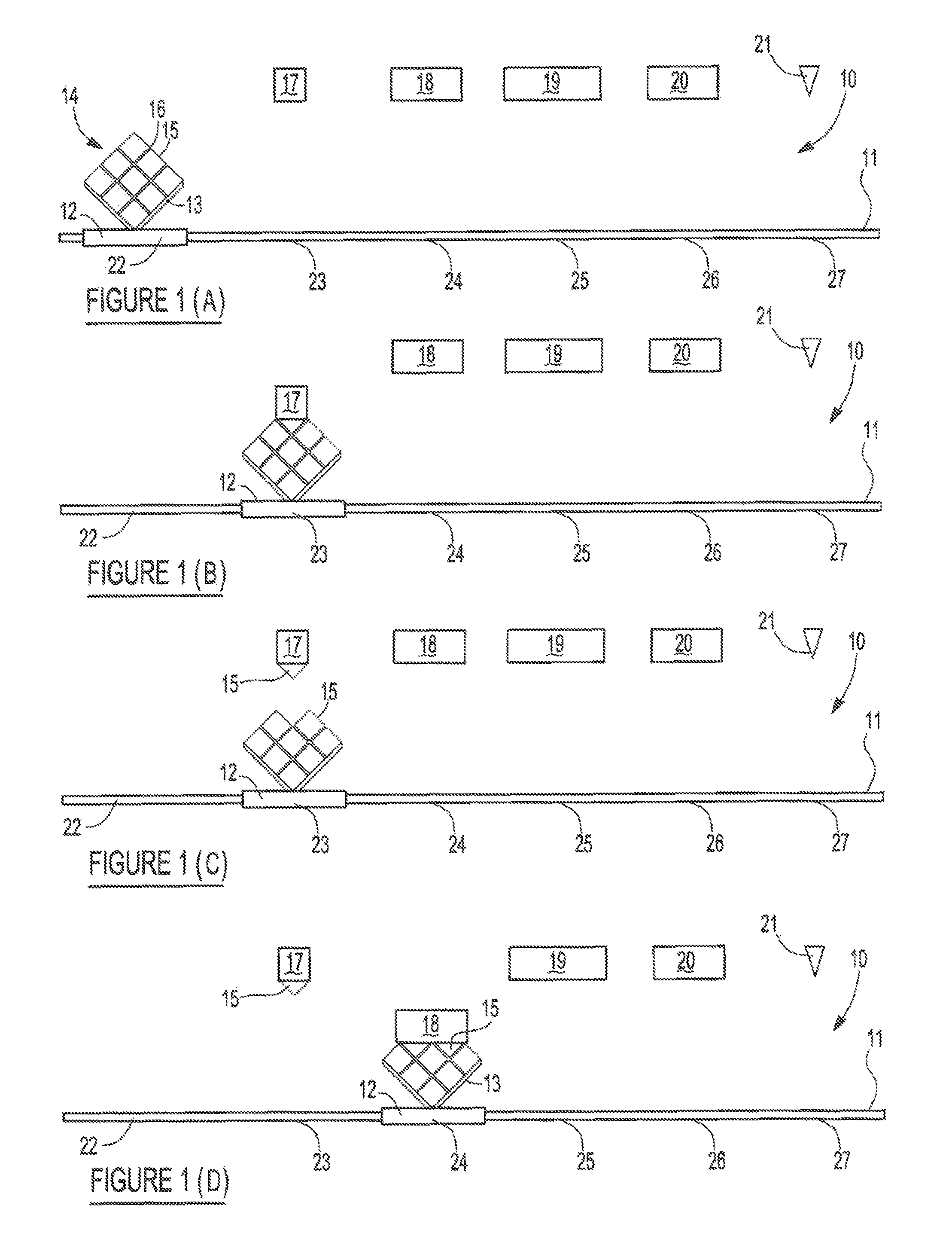
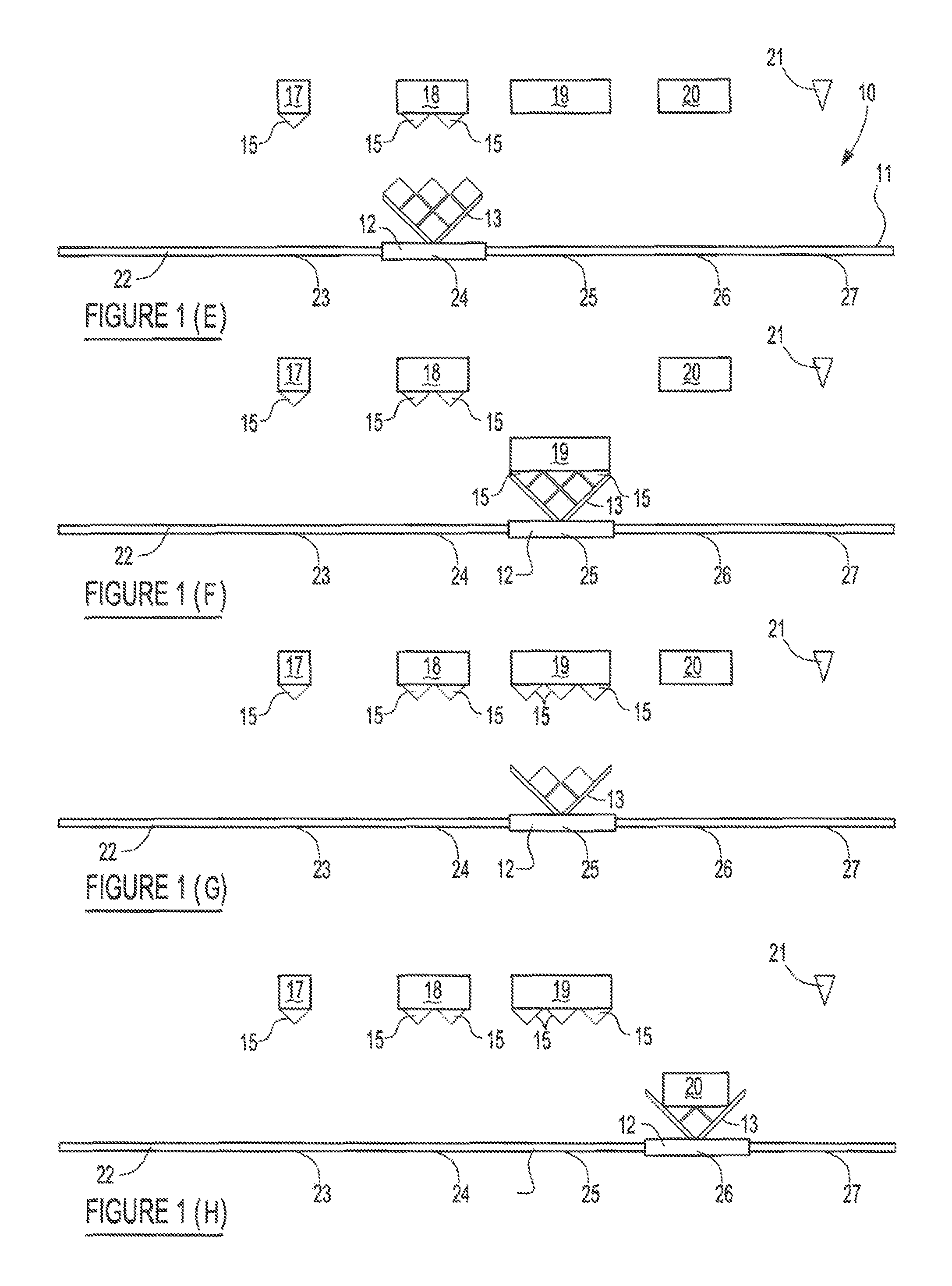
[0011]The invention relates to a method of assembling a plurality of ceramic filter segments into an array of ceramic filter segments which are bonded together using a cement of consistent thickness. Consistent thickness means that the cement layers disposed between two adjacent ceramic segments exhibit a thickness within a specified range and the variation of the thickness along the bonded adjacent surfaces is within a specified range of variation of the thickness. The size of the cera...


PUM

PropertyMeasurementUnit
thicknessaaaaaaaaaa
thicknessaaaaaaaaaa
thicknessaaaaaaaaaa

Abstract

A method comprising; a) assembling a plurality of ceramic filters, into an array wherein two or more of the outer surfaces of each filter are located adjacent to outer surfaces of other ceramic filters with removable spacers located between the adjacent surfaces of ceramic filters such that the spaces between, the adjacent surfaces are uniform m a work surface; b) removing sequentially one or more of the ceramic filters or horizontal rows of the ceramic filters and removing the spacers between adjacent surfaces until a single ceramic fitter or horizontal row remains; c) applying a cement layer to the outer surface of the single ceramic filter or horizontal row on the work surface; d) replacing the next adjacent ceramic filter or horizontal row of ceramic filters in the location the ceramic filler or horizontal row of ceramic filters were removed from; e) sequentially applying layers of cement to the outer surface of a ceramic filter or outer surfaces of a horizontal row of ceramic filters and replacing the next adjacent ceramic filter or horizontal, row of ceramic filters in the location or locations the ceramic filter or horizontal rows of ceramic filters were removed from, until all of the ceramic filters are replaced in the same position on the work surface with uniform cement layers located between all adjacent surfaces of rise ceramic filters.

Description

FIELD OF THE INVENTION[0001]The present invention relates generally to a process for bonding arrays of ceramic filters together such that the bond thickness between the ceramic filters is consistent.BACKGROUND OF THE INVENTION[0002]Diesel engines, because of the way they operate, emit soot particles or very fine droplets of condensate or a conglomerate of the two (particulates) as well a typical harmful gasoline engine exhausts (i.e., HC and CO). These “particulates” (herein Diesel soot), are rich in condensed, polynuclear hydrocarbons, some of which may be carcinogenic. As the awareness of the danger Diesel soot presents to health collides with the need for greater fuel efficiency that Diesel engines provide, regulations have been enacted curbing the amount of Diesel soot permitted to be emitted. To meet these challenges, soot filters have been used. When using such a filter, the filter must be periodically regenerated by burning off the soot. This burning of soot results in stress...

Claims


Application Information

Patent Timeline
Patent Type & Authority Patents(United States)
IPC IPC(8): B32B41/00C04B37/00B01D46/24
CPCC04B37/00B01D46/24B01D46/2418C04B37/005C04B35/185C04B38/0019C04B2235/46C04B2235/5208C04B2235/658C04B2235/78C04B2237/062C04B2237/064C04B2237/341C04B2237/343C04B2111/00793Y10T156/10C04B35/00C04B38/0006F01N3/022
Inventor PATT, JEREMY
Owner DOW GLOBAL TECH LLC
Why Eureka
Try Eureka