
Radiolucent electrode assembly

a technology of lead wire and assembly, which is applied in the field of radiolucent lead wire replacement assembly, can solve the problems of difficult to make the proper connection between the electrode and the telemetry unit, difficult to meet the needs of emergency situations, and difficult to restrict the patient's movement, etc., to achieve the effect of improving the radiolucency of these types of monitoring devices and increasing patient comfor

Active Publication Date: 2015-12-15
LIFESYNC
View PDF10 Cites 3 Cited by
  • Summary
  • Abstract
  • Description
  • Claims
  • Application Information

AI Technical Summary

Benefits of technology

The present invention meets the need for a radiolucent electrode or sensor assembly for medical monitoring. The seamless and continuous electrical path around the electrode or sensor creates stronger signals and reduces interruptions and the risk of burns. The assembly is placed on the chest and can be routed outside the area to be imaged. The flexible arms or extensions of the assembly make it easy to relocate sensors, and the electrode connector is fixed in a location that is not critical for the imaging. Overall, the invention improves the reliability and accuracy of medical monitoring while minimizing patient discomfort.

Problems solved by technology

Restriction of the patient's movement is oftentimes cumbersome and uncomfortable for a patient and the attending medical staff.
It is also ill-suited for emergency situations during which a patient's body must be rapidly moved to a variety of positions and transported to several locations.
Because each electrode or sensor is individually connected to the telemetry unit by an individual lead wire or cable, the several lead wires or cables become confusingly intertwined making it difficult to make the proper corresponding connections between the electrodes and the telemetry unit.
Also, because each electrode or sensor is placed separately on the patient, one at a time in a sequence, the chances of acquiring an inaccurate signal due to improper placement on the patient are high.
Additionally, the motion of the individual current carrying lead wires in relation to each other causes the generation of electrical artifacts in the transmitted signal.
However, these types of fully-integrated electrode assemblies have several disadvantages stemming from their high cost and lack of flexibility in permitting alternative placement of the electrodes.
With respect to fully-integrated electrode assemblies, in order to dispose of a failed electrode or sensor element, the entire assembly must impractically be discarded.
These gels will rapidly dry out and lose their conductivity.
Several disadvantages also stem from the use of fully-integrated electrode assemblies.
For example, because the electrode or conductive surfaces are generally fixed in one position, the electrode assembly cannot be adapted to varying body sizes.
Because of this lack of adaptability, applications that require placing the electrodes at un-conventional positions on the body would require manufacturing several separate configurations of the assembly.
Also, because the electrode assembly is fully self-contained, the patient must uncomfortably bear the weight of the entire system, including the telemetry circuitry, on the chest.
For neonatal and elderly patients, who tend to be relatively weak, have lower body weight, and generally thinner skin or more sensitive skin than do patients of other ages, this can be very uncomfortable.
Furthermore, the power source (e.g. batteries), telemetry circuitry or other electronics may generate external heat that can add to the discomfort or potentially burn or irritate a patient's skin.
Because the shape and size of conventional electrodes or sensors are not standardized, they are not universally compatible with many of the wires, leads or chest assemblies used in physiological data collection systems.
These spring-loaded pieces are relatively expensive and cannot be amortized over the life of a disposable chest assembly.
Also, because it is important that any fastener fit tightly to the electrode or sensor in order to avoid a conductivity gap, the amount of pressure needed to snap the pieces together can be physically difficult.
Conventional wired and wireless ECG systems, particularly those with chest-worn components, significantly interfere with the normal use and viewing of an X-ray film, fluoroscopic or other image that is created by electromagnetic radiation.
Due to the desirability of using good conductors, such as metals, in the chest-worn electrodes, sensors and other components to provide a good electrical path for the sensor, these components are oftentimes substantially not radiolucent or radiotransparent and appear as blemishes or shadows or at worse, are completely opaque on the diagnostic image.
Also, because the chest assemblies typically span the entire chest, they greatly impair access for surgical procedures and usually need to be removed during surgery and other medical treatments that require unimpeded access to the chest area.
Also, thin foils or paints which may provide the desired degree of radiolucency are more fragile than solid metallic parts and are more easily worn down or chipped from abrasion.
However, these polymers are generally composed of very thin, carbon filaments or particles thereby having the characteristic of high impedance such that a large amount of external heat is generated by a flowing current.
As such, carbon based conductors alone will rarely withstand an external defibrillation current applied to the body.
Unfortunately the application of the silver / silver chloride negatively affects the electrode's radiolucency and may make it opaque.
Thus, the carbon or graphite-filled polymers or cables are relatively thick in comparison making them relatively unwieldy when worn by a patient.
Further, the increased thickness of the materials reduces the radiolucency and shows up unsatisfactorily on the resulting images.
This is particularly problematic with depth-capturing images such as computed tomography (CT) scans.

Method used


Image

  • Radiolucent electrode assembly
  • Radiolucent electrode assembly
  • Radiolucent electrode assembly

Examples


Embodiment Construction

[0047]For a better understanding of the present invention, reference may be had to the following detailed description taken in conjunction with the appended claims and the accompanying drawings.

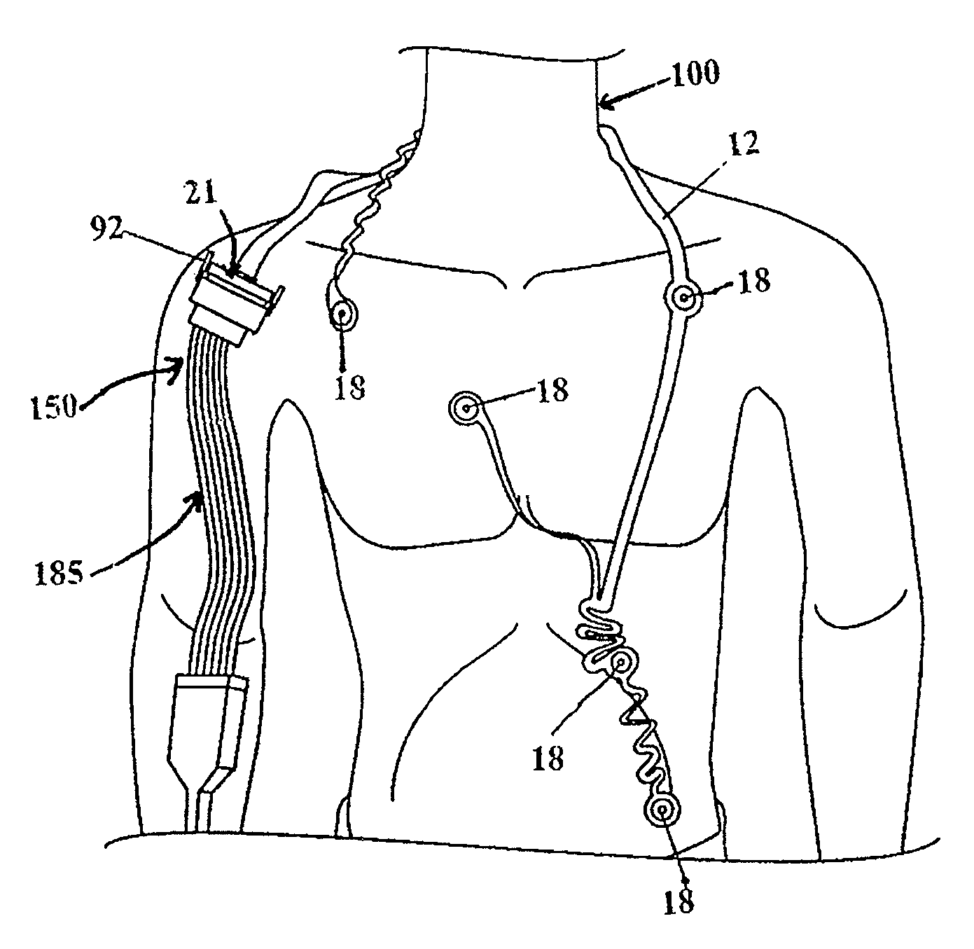
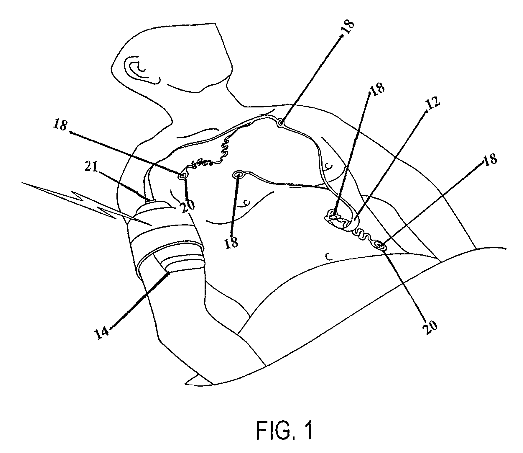
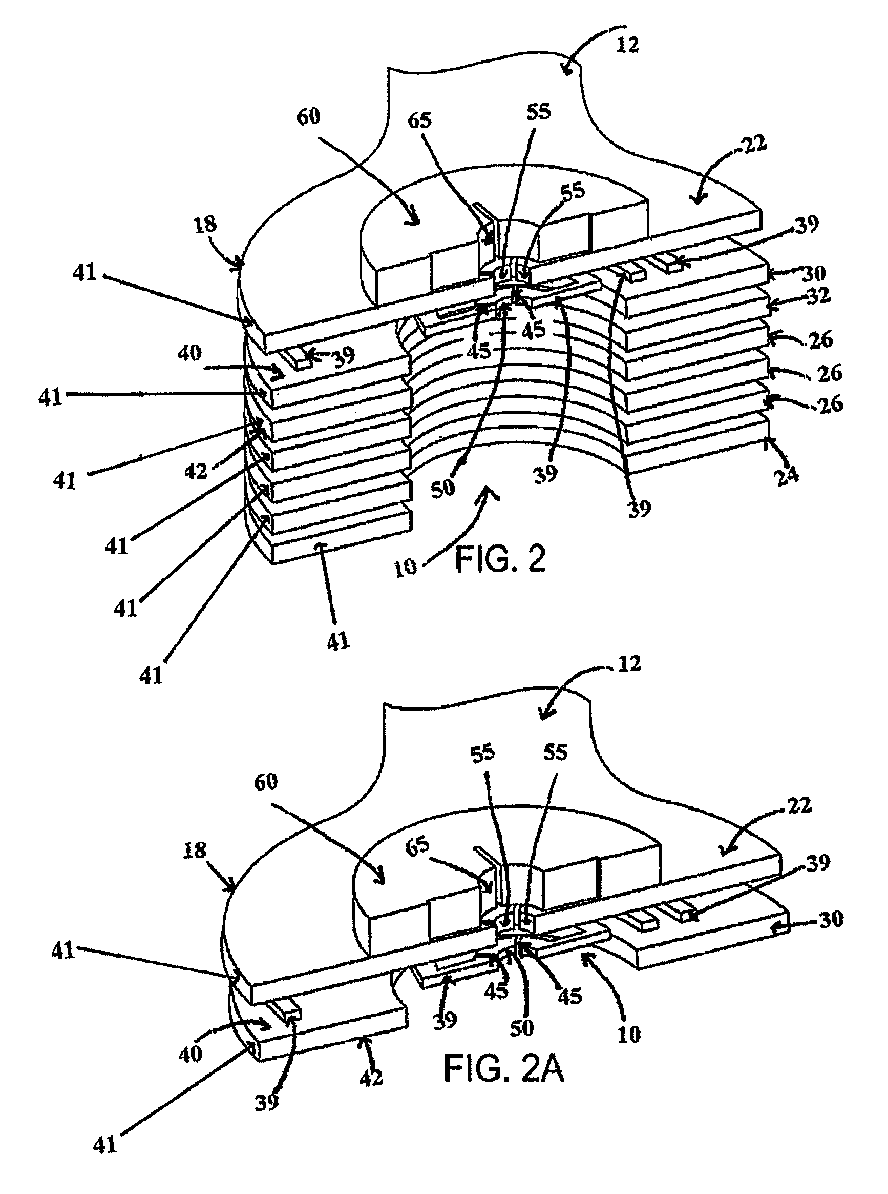
[0048]Referring to FIG. 1, the chest assembly 12 is preferably a one-piece flexible circuit that connects a plurality of electrode connectors 18 whereby the electrode connectors 18 are configured to connect to electrodes 20 or electrically conductive adhesives. Preferably, the electrode connectors 18 have snap terminals that connect to electrodes 20 having snap terminals. As shown in detail in FIG. 3, each electrode connector 18 connects to an electrically conductive element or trace 39 for transmitting electrical signals. The electrically conductive elements or traces 39 run along the chest assembly 12 and connect to a chest assembly connector 21.

[0049]Alternatively, the chest assembly 12 may be constructed with electrode conductors, instead of electrode connectors. In such an embodiment, ea...


PUM


Abstract

A lightweight, disposable and substantially radiolucent electrode or sensor assembly for that universally connects to separate, non-integrated electrodes or sensors for the monitoring of the physiological parameters of a live subject wherein the electrode assembly is comprised of one or more radiolucent electrical connectors for connecting the electrode assembly to the sensors. The present invention also discloses a method of positioning the electrode assembly on a patient whose physiological signs are being monitored such that access to the patient's chest is substantially unimpeded so as not to obstruct the electromagnetic imaging of the patient's chest, the application of defibrillation paddles or surgical procedures that require access to the chest area.

Description

PRIORITY CLAIM[0001]This application claims priority to corresponding U.S. Provisional Application No. 60 / 897,390, filed on Jan. 25, 2007, which incorporates U.S. patent application Ser. No. 09 / 998,733, filed on Nov. 30, 2001, now issued as U.S. Pat. No. 7,197,357, Ser. No. 10 / 439,356, filed on May 16, 2003, Ser. No. 11 / 077,934, filed on Mar. 11, 2005, Ser. No. 11 / 105,230, filed on Apr. 12, 2005, Ser. No. 11 / 105,231, filed on Apr. 12, 2005, Ser. No. 11 / 105,232, filed on Apr. 12, 2005, and Ser. No. 09 / 908,509, filed on Jul. 17, 2001, now issued as U.S. Pat. No. 6,611,705, the disclosure and contents of which are expressly incorporated herein by reference.FIELD OF INVENTION[0002]The present invention relates to a radiolucent lead wire replacement assembly for the monitoring of physiological data and to architectures having improved radiolucency for connecting flat printed circuits to sensors.BACKGROUND OF THE INVENTION[0003]The ability to monitor the physiological parameters of a live...

Claims


Application Information

Patent Timeline
Patent Type & Authority Patents(United States)
IPC IPC(8): A61B5/04A61B5/0408A61N1/00A61B5/308A61B5/276
CPCA61B5/0408A61B5/04085A61B2560/045A61B2562/164A61B2562/0215A61B5/6822A61B5/6823A61B2562/0285A61B2562/222A61B2562/226A61B2562/227A61B5/259A61B5/25A61B5/282A61B5/276A61B5/303A61B5/291
Inventor QUINTANAR, FELIXHENDRY, KALNGUYEN, TOMMUSER, ANDREW
Owner LIFESYNC
Learn More