Method for joining a composite sheet to a metallic substrate

a composite sheet and metallic substrate technology, applied in the direction of arc welding apparatus, resistance welding apparatus, laser beam welding apparatus, etc., can solve problems such as unstable arcs, and achieve the effect of cost-effective and effective vibration damping

Active Publication Date: 2015-12-15
THYSSENKRUPP STEEL EURO AG
View PDF8 Cites 5 Cited by
  • Summary
  • Abstract
  • Description
  • Claims
  • Application Information

AI Technical Summary

Benefits of technology

[0007]By forming the joining element as a sleeve, the plastic layer of the composite sheet is separated from the joining area, so that it does not affect the subsequent joining process. By joining the sleeve to the composite sheet in a form-fit and force-fit manner, a durable connection between the sleeve and the composite sheet is ensured, so that when the sleeve is subsequently joined to the substrate the composite sheet is also durably joined to the substrate. By joining the sleeve to the substrate using a filler material, which is arranged inside the sleeve, the composite sheet can be durably joined to the substrate without the plastic layer of the composite sheet affecting the joining process. As a result, a better join is achieved between the composite sheet and the substrate. In addition, the joining process can take place without the plastic layer being damaged by a too high input of heat. The sleeve is deformed, for example, by pressing. Subsequently, on the open side of the composite sheet, the sleeve can either protrude or be flush with the surface of the composite sheet.
[0029]The use of a structure according to the invention for subsequent sound insulation makes cost-efficient and effective vibration damping possible, wherein a firm join can be ensured between the vibrating component and the damping sheet.

Problems solved by technology

The disadvantage of welding processes of this type is that the plastic material has an indirect effect on the welding process and hence results in an unstable arc.

Method used


Image

  • Method for joining a composite sheet to a metallic substrate
  • Method for joining a composite sheet to a metallic substrate
  • Method for joining a composite sheet to a metallic substrate

Examples


Embodiment Construction

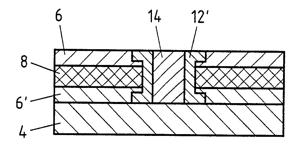
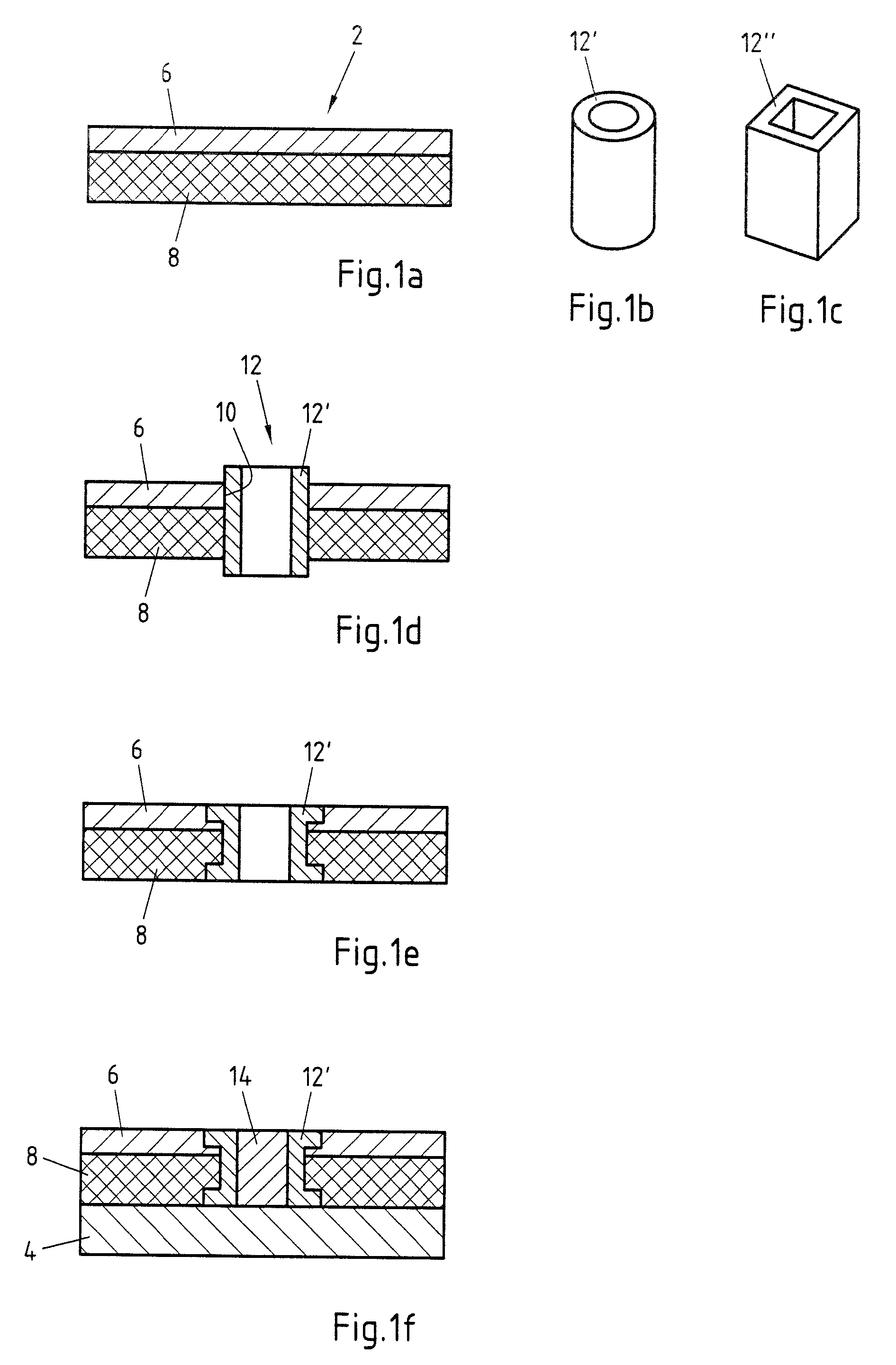
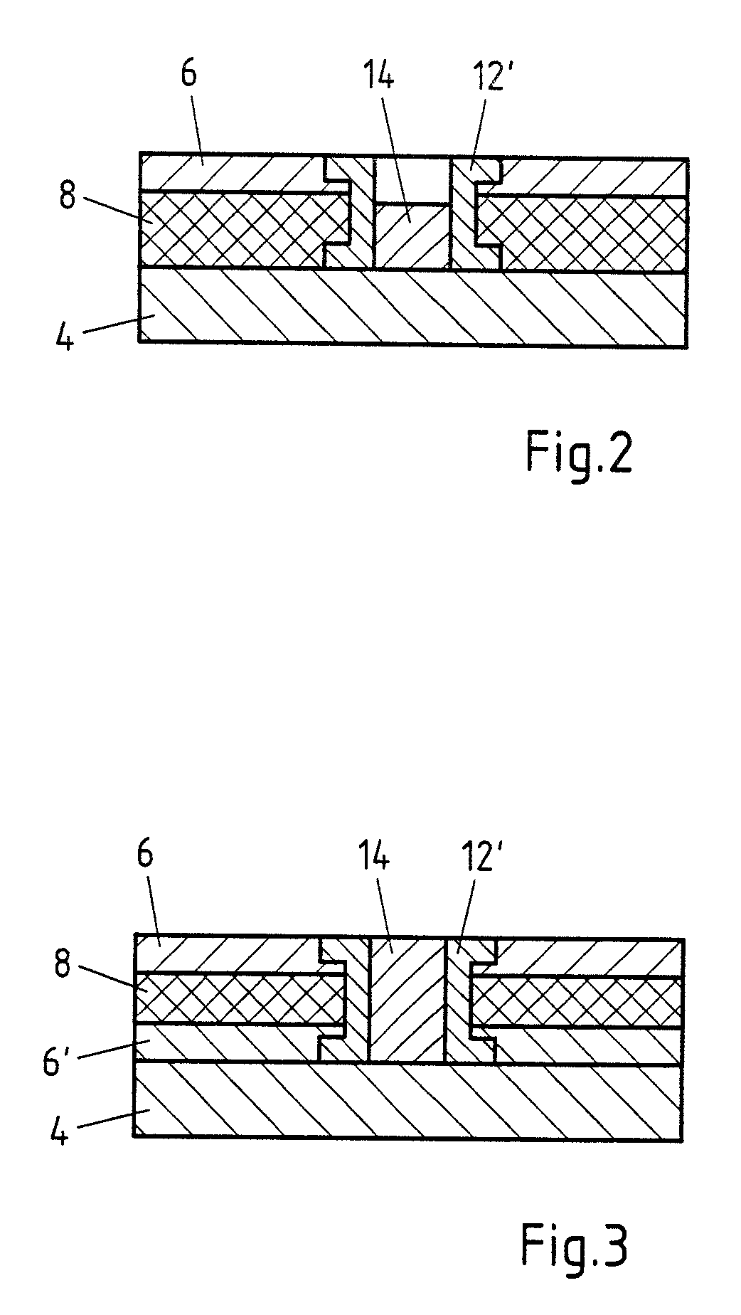
[0034]FIGS. 1a to 1f respectively show individual steps of an exemplary embodiment of the method according to the invention. Specifically, FIG. 1a shows an exemplary embodiment of a composite sheet 2 which has a plastic layer 8 and a metallic top layer 6. The thickness of the plastic layer 8 is greater than the thickness of the metallic top layer 6 in the exemplary embodiment shown. It can, however, also be thinner. On the one hand, a large saving in weight can be obtained, but, in addition, the vibration-damping properties of the composite sheet 2 can also be improved.

[0035]FIGS. 1b and 1c show two exemplary embodiments of the sleeve 12′ which is inserted as a joining element 12 into the composite sheet 2. Both exemplary embodiments have the form of a hollow body. The cross-sectional area of the sleeve 12′ is round in FIG. 1b and the cross-sectional area of the sleeve 12″ in FIG. 1c is quadrangular. Of course, a sleeve 12′ with any other cross-sectional area, for example a polygona...


PUM

PropertyMeasurementUnit
thicknessaaaaaaaaaa
metallicaaaaaaaaaa
sound absorptionaaaaaaaaaa

Abstract

The invention relates to a method for joining a composite sheet to a metallic substrate, wherein the composite sheet has at least one metallic top layer and at least one non-metallic layer which consists of a plastic material, wherein an opening is introduced into the composite sheet, and wherein at least one joining element is provided which is inserted into the opening of the composite sheet. A method for joining a composite sheet to a metallic substrate with process reliability and of specifying a corresponding structure is achieved by forming the joining element as a metallic sleeve, wherein the metallic sleeve is deformed, so that it joins together with the composite sheet in a form-fit and force-fit manner, and wherein the metallic sleeve is firmly bonded to the substrate with the end pointing towards the substrate using a filler material, wherein the filler material is arranged inside the sleeve.

Description

CROSS-REFERENCE TO RELATED PATENT APPLICATIONS[0001]This patent application is a continuation of PCT / EP2013 / 053774, filed Feb. 26, 2013, which claims priority to German Application No. 10 2012 102 286.0, filed Mar. 19, 2012, the entire teachings and disclosure of which are incorporated herein by reference thereto.BACKGROUND OF THE INVENTION[0002]The invention relates to a method for joining a composite sheet to a metallic substrate, wherein the composite sheet has at least one metallic top layer and at least one non-metallic layer which consists of a plastic material, wherein an opening is introduced into the composite sheet, and wherein at least one joining element is provided which is inserted into the opening of the composite sheet. In addition, the invention relates to a structure, in particular produced using an embodiment of the above mentioned method, comprising a composite sheet and a substrate, wherein the composite sheet has at least one metallic top layer and at least one...

Claims


Application Information

Patent Timeline
Patent Type & Authority Patents(United States)
IPC IPC(8): B23K11/16B21D39/03B23K11/00B23K1/00B32B3/08B32B15/20B32B15/18B32B15/08B23K9/00B23K26/00B32B3/26B32B9/04B32B15/04
CPCB23K11/002B21D39/03B23K1/0008B23K9/0026B23K26/0093B32B3/08B32B3/266B32B9/042B32B15/043B32B15/08B32B15/18B32B15/20B23K2203/16B32B2307/102Y10T29/49732Y10T428/24322B23K2103/16B23K2103/172
Inventor BEENKEN, HEIKOOHSE, PETER
Owner THYSSENKRUPP STEEL EURO AG
Why Eureka
Try Eureka