Low NOx burner apparatus and method

a low-nosub>x/sub>burner and burner technology, applied in lighting and heating apparatus, combustion types, combustion using lumps and pulverizing fuel, etc., can solve problems such as thermal nosub>x/sub>reduction, and achieve less complex, less expensive, and more stable operation

Active Publication Date: 2015-12-29
ZEECO
View PDF8 Cites 3 Cited by
  • Summary
  • Abstract
  • Description
  • Claims
  • Application Information

AI Technical Summary

Benefits of technology

[0011]The present invention provides a low NOx burner apparatus and method which satisfy the needs and alleviate the problems discussed above. The inventive burner and method are capable of providing NOx emission levels of 10 parts per million by volume (ppmv) or less (preferably 7 ppmv or less) based on the total volume of combustion gas product produced by the burner. The inventive low NOx burner also provides much more stable operation and is less complex and less costly than the low NOx burner systems currently available. Moreover, the inventive burner is much simpler to maintain and control and provides a desirably broad available operating range. In this regard, the inventive burner can provide a turndown ratio in the range of from about 10:1 to about 20:1 or more.
[0012]The inventive burner and method also greatly reduce the need for metal components within the throat of the burner, thus allowing the size of the burner to be significantly reduced. This, coupled with the desirably broad turndown ratio provided by the inventive burner, allows the furnace operator to achieve and maintain more optimum, stable heat flux characteristics and also allows the inventive burner to be more easily sized as needed. Thus, the inventive burner can be conveniently used in existing heaters, boilers, etc. to replace most existing conventional or staged fuel burners with, at most, only minor modifications to the furnace structure.
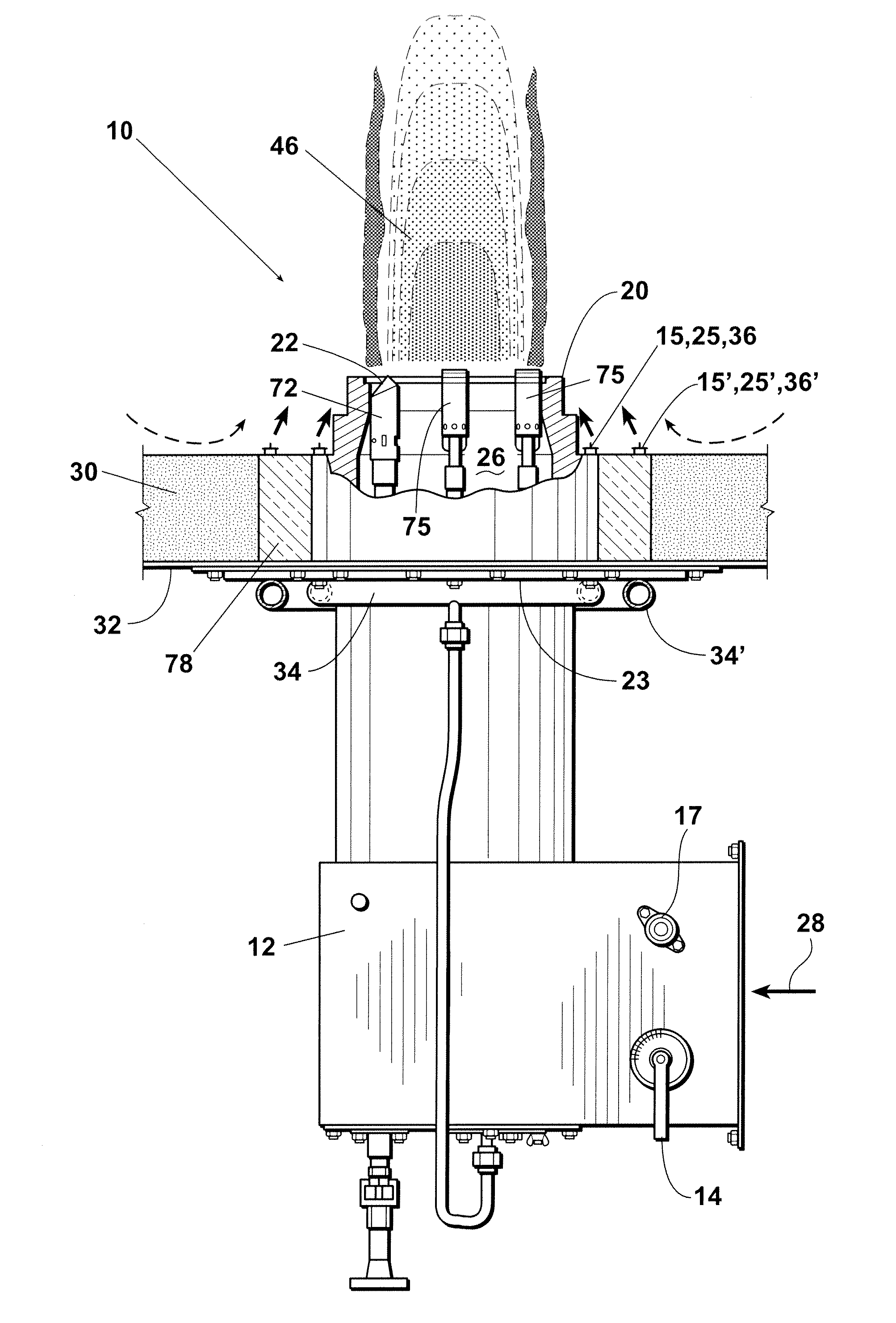
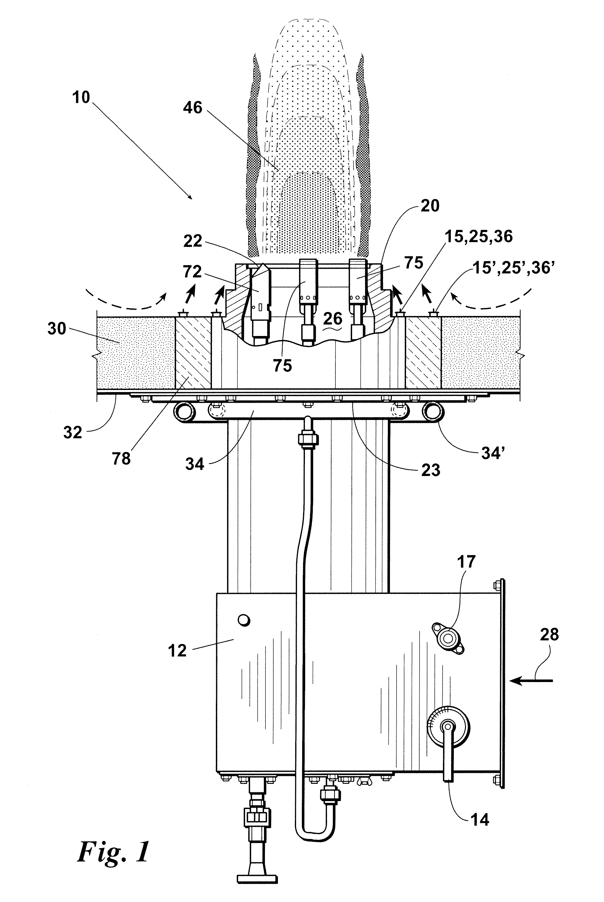
[0016]In another aspect, the inventive burner assembly preferably comprises: a burner wall having an air passageway therethrough and a combustion region beginning at or near the outer end of the burner wall; a series of primary fuel gas ejection tips or other primary ejection structures which partially surround, substantially surround, or completely surround the burner wall for ejecting primary fuel gas outside the burner wall such that at least most of the primary fuel gas is received in the combustion region; and a series of secondary fuel gas ejection tips or other secondary ejection structures spaced radially outward from the series of primary ejectors which also partially surround, substantially surround, or completely surround the burner wall for ejecting secondary fuel gas outside of the burner wall such that at least most of the secondary fuel gas is received in the combustion region. The primary gas and secondary gas pass through and mix with the inert products of combustion (flue gas) within the furnace housing a “free jet” mixing method. The “free jet” method of mixing maximizes the amount of inert products of combustion which combine with the fuel gas prior to complete combustion.
[0023]The inventive burner is preferably an “Internal Flue Gas Recirculation” (IFGR) burner that mixes fuel gas together with the inert products of combustion inside the furnace housing to produce low emissions with preferably little or no “External Flue Gas Recirculation” (EFGR). In addition, the use of staged fuel gas ejection in the inventive burner assembly further reduces NOx emissions by increasing the amount of inert products of combustion mixed with the fuel gas.
[0024]Also, the inventive burner increases the amount of “Internal Flue Gas Recirculation” (IFGR) to thereby reduce thermal NOx emissions without sacrificing burner performance with respect to flame length, turndown ratio, and stability. The maximization of IFGR to achieve low NOx emissions also eliminates or significantly reduces many of the problems experienced by other burners which must rely on high levels of “External Flue Gas Recirculation” (EFGR) in order to achieve reduced emissions. Compared to burners which use EFGR, the inventive burner reduces the blower power usage, increases the burner turndown ratio, reduces maintenance costs and requirements, and improves flame quality.
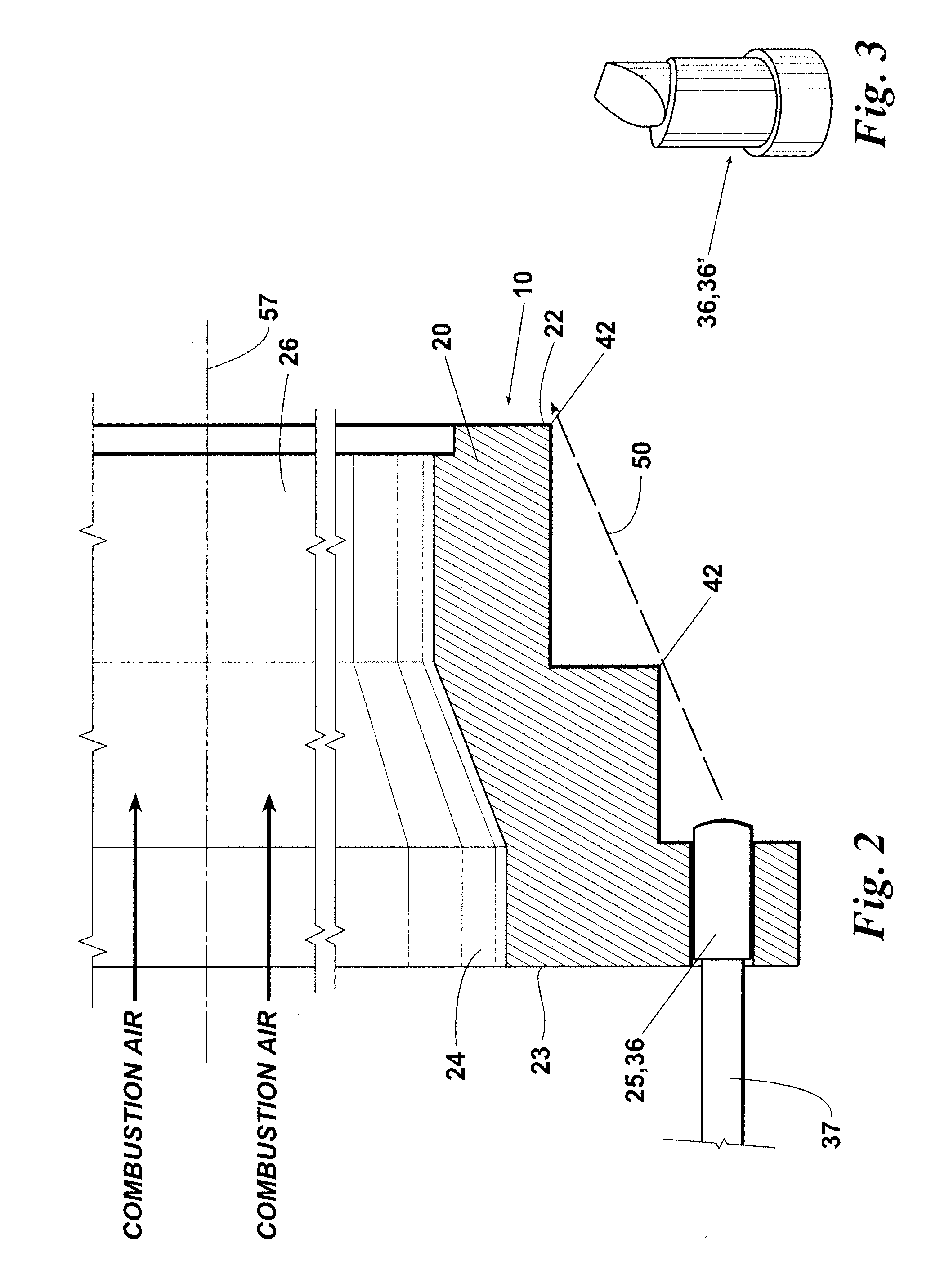
[0025]The inventive burner operates in a manner whereby both the primary fuel gas and the secondary fuel gas used in the burner must pass through and mix with the products of combustion (flue gas) within the furnace before complete combustion occurs. This mixing, or fuel conditioning, allows the peak flame temperature of the fuel mixture to be reduced and the thermal NOx emissions to be lowered. In addition to a series / row of surrounding exterior primary gas tips, the inventive burner also uses a second series / row (or multiple additional series / rows) of exterior surrounding gas tips, called secondary gas tips, wherein the secondary series is spaced radially outwardly from the primary series such that the secondary fuel gas ejected from the secondary tips must travel along a longer path through the internal products of combustion within the furnace housing before reaching the combustion region which preferably begins at or near the outer end of the burner wall. Since the fuel gas passes through more inert products of combustion due to the increased distance to the combustion region, more mixing occurs which changes the composition of the fuel such that the resulting reconditioned fuel mixture is preferably around 80% to 90% inert. The combustion of the highly reconditioned fuel gas thus occurs in a manner which provides more uniform heat distribution at a lower peak temperature with less thermal NOx emissions.

Problems solved by technology

However, when the fuel is burned under less than ideal conditions, such as in a high temperature environment, nitrogen present in the combustion air reacts with oxygen to produce nitrogen oxides (NOx).
However, thermal NOx reduction is generally achieved by delaying the rate of combustion.

Method used


Image

  • Low NO<sub>x </sub>burner apparatus and method
  • Low NO<sub>x </sub>burner apparatus and method
  • Low NO<sub>x </sub>burner apparatus and method

Examples


Embodiment Construction

[0048]Before explaining the present invention in detail, it is important to understand that the invention is not limited in its application to the details of the preferred embodiments and steps described herein. The invention is capable of other embodiments and of being practiced or carried out in a variety of ways. It is to be understood that the phraseology and terminology employed herein is for the purpose of description and not of limitation.

[0049]It will also be understood by those of ordinary skill in the art that, unless otherwise specified, the inventive features, structures, and steps discussed herein can be advantageously employed using any number of exterior fuel ejection nozzles, each having one or any other number of flow ejection ports provided therein. In addition, the inventive burners described herein can be oriented upwardly, downwardly, horizontally, or at generally any other desired operating angle.

[0050]Referring now to the drawings, FIGS. 1 and 2 depict an embo...


PUM


Abstract

A burner apparatus for a furnace system and a method of burner operation. The burner has a series of fuel ejection structures which at least partially surround the burner wall for ejecting fuel into a combustion region projecting from the forward end of the burner wall. The ejection structures preferably eject fuel outside of the burner wall at alternating angles. Further, the burner apparatus preferably includes at least one additional series of fuel ejection structures which is spaced radially outward from the first series of ejection structures.

Description

[0001]This application claims the benefit of U.S. Provisional Patent Application Ser. No. 61 / 558,281 filed on Nov. 10, 2011, and incorporates said provisional application by reference into this document as if fully set out at this point.FIELD OF THE INVENTION[0002]The present invention relates to burner assemblies and to methods and apparatuses for reducing NOx emissions from burners of the type used in process heaters, boilers, and other fired heating systems.BACKGROUND OF THE INVENTION[0003]Many industrial applications require large scale generation of heat from burners for process heaters, boilers, or other fired heating systems. If the burner fuel is thoroughly mixed with air and combustion occurs under ideal conditions, the resulting combustion products are primarily carbon dioxide and water vapor. However, when the fuel is burned under less than ideal conditions, such as in a high temperature environment, nitrogen present in the combustion air reacts with oxygen to produce nit...

Claims


Application Information

Patent Timeline
Patent Type & Authority Patents(United States)
IPC IPC(8): F23D14/22F23C9/00F23D14/84
CPCF23D14/22F23D14/84F23C9/006F23C2202/20
Inventor ZINK, DARTON J.ISAACS, REX K.GUARCO, JOHN PHILIPBEALE, FRANK E.MCDONALD, JOHNLITTLE, CODY L.MARTY, SETHROBERTS, RYAN
Owner ZEECO
Why Eureka
Try Eureka