Low NOX burner apparatus and method

a burner and low nox technology, applied in lighting and heating apparatus, combustion types, combustion using lumps and pulverizing fuel, etc., can solve problems such as no/sub>x reduction, and achieve the effects of less complex, less expensive, and more stable operation

Active Publication Date: 2013-05-16
ZEECO
View PDF6 Cites 16 Cited by
  • Summary
  • Abstract
  • Description
  • Claims
  • Application Information

AI Technical Summary

Benefits of technology

[0011]The present invention provides a low NOx burner apparatus and method which satisfy the needs and alleviate the problems discussed above. The inventive burner and method are capable of providing NOx emission levels of 10 parts per million by volume (ppmv) or less (preferably 7 ppmv or less) based on the total volume of combustion gas product produced by the burner. The inventive low NOx burner also provides much more stable operation and is less complex and less costly than the low NOx burner systems currently available. Moreover, the inventive burner is much simpler to maintain and control and provides a desirably broad available operating range. In this regard, the inventive burner can provide a turndown ratio in the range of from about 10:1 to about 20:1 or more.

Problems solved by technology

However, when the fuel is burned under less than ideal conditions, such as in a high temperature environment, nitrogen present in the combustion air reacts with oxygen to produce nitrogen oxides (NOx).
However, thermal NOx reduction is generally achieved by delaying the rate of combustion.

Method used


Image

  • Low NOX burner apparatus and method
  • Low NOX burner apparatus and method
  • Low NOX burner apparatus and method

Examples


Embodiment Construction

[0048]Before explaining the present invention in detail, it is important to understand that the invention is not limited in its application to the details of the preferred embodiments and steps described herein. The invention is capable of other embodiments and of being practiced or carried out in a variety of ways. It is to be understood that the phraseology and terminology employed herein is for the purpose of description and not of limitation.

[0049]It will also be understood by those of ordinary skill in the art that, unless otherwise specified, the inventive features, structures, and steps discussed herein can be advantageously employed using any number of exterior fuel ejection nozzles, each having one or any other number of flow ejection ports provided therein. In addition, the inventive burners described herein can be oriented upwardly, downwardly, horizontally, or at generally any other desired operating angle.

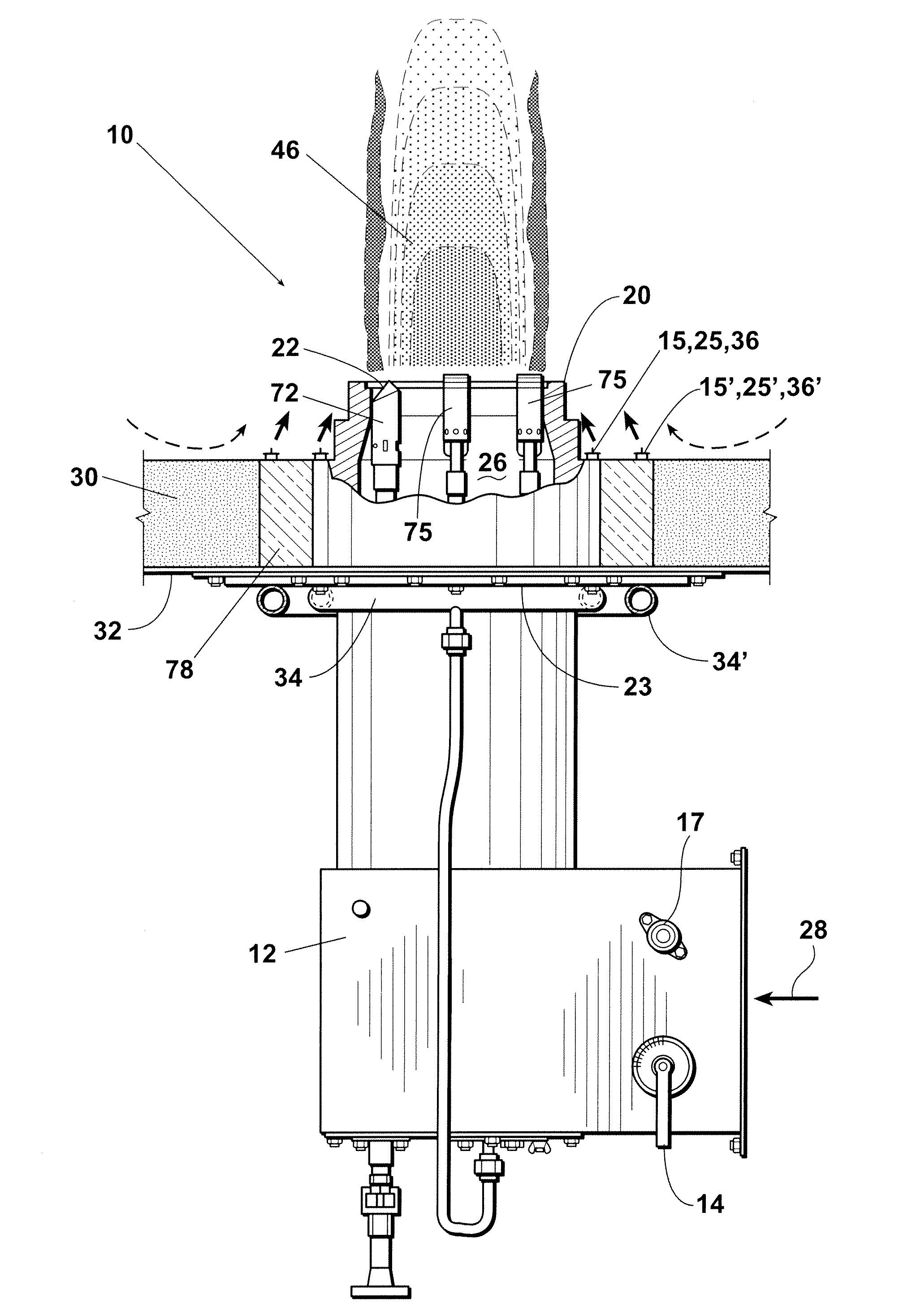
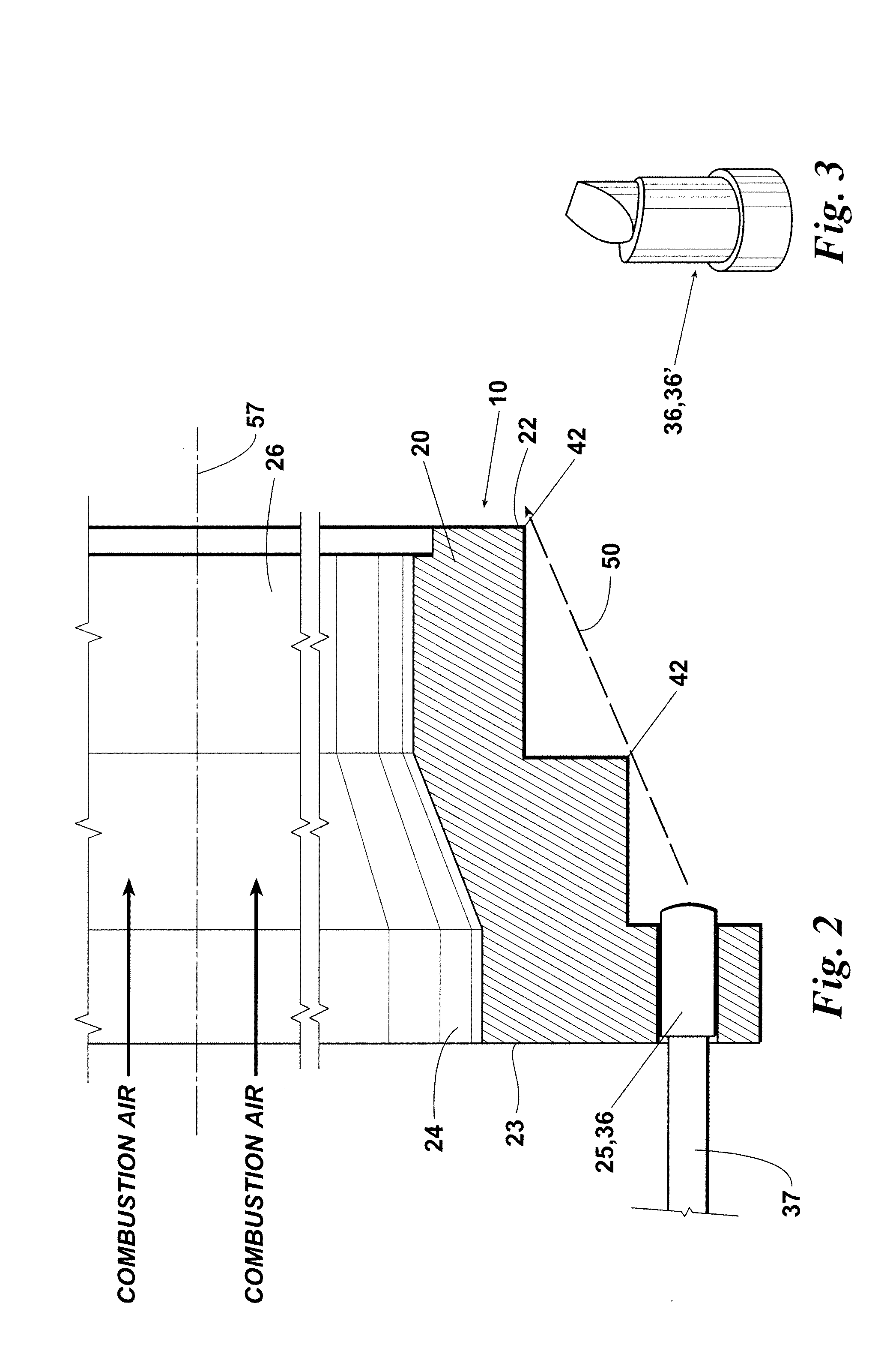
[0050]Referring now to the drawings, FIGS. 1 and 2 depict an embo...


PUM


Abstract

A burner apparatus for a furnace system and a method of burner operation. The burner has a series of fuel ejection structures which at least partially surround the burner wall for ejecting fuel into a combustion region projecting from the forward end of the burner wall. The ejection structures preferably eject fuel outside of the burner wall at alternating angles. Further, the burner apparatus preferably includes at least one additional series of fuel ejection structures which is spaced radially outward from the first series of ejection structures.

Description

[0001]This application claims the benefit of U.S. Provisional Patent Application Ser. No. 61 / 558,281 filed on Nov. 10, 2011, and incorporates said provisional application by reference into this document as if fully set out at this point.FIELD OF THE INVENTION[0002]The present invention relates to burner assemblies and to methods and apparatuses for reducing NOx emissions from burners of the type used in process heaters, boilers, and other fired heating systems.BACKGROUND OF THE INVENTION[0003]Many industrial applications require large scale generation of heat from burners for process heaters, boilers, or other fired heating systems. If the burner fuel is thoroughly mixed with air and combustion occurs under ideal conditions, the resulting combustion products are primarily carbon dioxide and water vapor. However, when the fuel is burned under less than ideal conditions, such as in a high temperature environment, nitrogen present in the combustion air reacts with oxygen to produce nit...

Claims


Application Information

Patent Timeline
Patent Type & Authority Applications(United States)
IPC IPC(8): F23D14/22F23D14/84
CPCF23D14/22F23C2202/20F23C9/006F23D14/84
Inventor ZINK, DARTON J.ISAACS, REX K.GUARCO, JOHN PHILIPBEALE, FRANK E.MCDONALD, JOHNLITTLE, CODY L.MARTY, SETHROBERTS, RYAN
Owner ZEECO
Why Eureka
Try Eureka