Motor drive method, motor drive device, and brushless motor

a motor drive and motor technology, applied in the direction of motor/generator/converter stopper, electronic commutator, dynamo-electric converter control, etc., can solve the problem of surge energy not being absorbed more, load dump generation, etc., to prevent the power supply voltage supply from increasing, increase the current flowing through the coil, and prevent the effect of voltage increas

Active Publication Date: 2015-12-29
PANASONIC INTELLECTUAL PROPERTY MANAGEMENT CO LTD
View PDF17 Cites 5 Cited by
  • Summary
  • Abstract
  • Description
  • Claims
  • Application Information

AI Technical Summary

Benefits of technology

[0008]Thus, when the power supply voltage increases and becomes an overvoltage exceeding the predetermined voltage due to an effect of a noise, for example, the motor changes the advance angle amount to increase the current amount and absorb energy of the increased overvoltage while maintaining a present rotational operation without changing the present rotational operation such as the rotating speed, and as a result, a voltage of a power supply line can be prevented from increasing.
[0010]Thus, when the power supply voltage does not exceed the predetermined voltage, the current amount of the coil is decreased to promote efficiency and lower a noise, and when it exceeds the predetermined voltage, the voltage of the power supply line can be prevented from increasing.
[0013]According to this configuration, when the power supply voltage increases and becomes an overvoltage exceeding the predetermined voltage due to the effect of the noise, for example, the motor changes the advance angle amount to increase the current amount and absorb energy of the increased overvoltage without changing the present rotational operation such as the rotating speed, and as a result, the voltage of the power supply line can be prevented from increasing.
[0015]According to this configuration, the brushless motor is provided with the function to prevent the power supply voltage supplied from the power supply line from increasing.
[0016]As described above, according to the method for driving the motor, the motor drive device, and the brushless motor in the present invention, when the power supply voltage becomes the overvoltage due to the effect of the noise, for example, the advance angle amount is changed to increase the current amount flowing through the coil. Therefore, the method for driving the motor, the motor drive device, and the brushless motor can prevent the voltage increase on the power supply line generated while the motor is energized and driven, and perform operations in stable power supply circumstances.

Problems solved by technology

Furthermore, when the mounted buttery is cut off for some reasons while an engine is driven, it is known that a transient phenomenon called load dump is generated, and a high voltage is generated on a power supply line.
However, the above-described technique is configured such that when the surge is generated while a blower motor is stopped, the blower motor is energized and driven, and surge energy is absorbed by the blower motor.
Therefore, when the surge is generated while the blower motor is energized and driven, the problem is that the surge energy cannot be absorbed more than the surge energy due to the energizing and driving.

Method used


Image

  • Motor drive method, motor drive device, and brushless motor
  • Motor drive method, motor drive device, and brushless motor
  • Motor drive method, motor drive device, and brushless motor

Examples


first exemplary embodiment

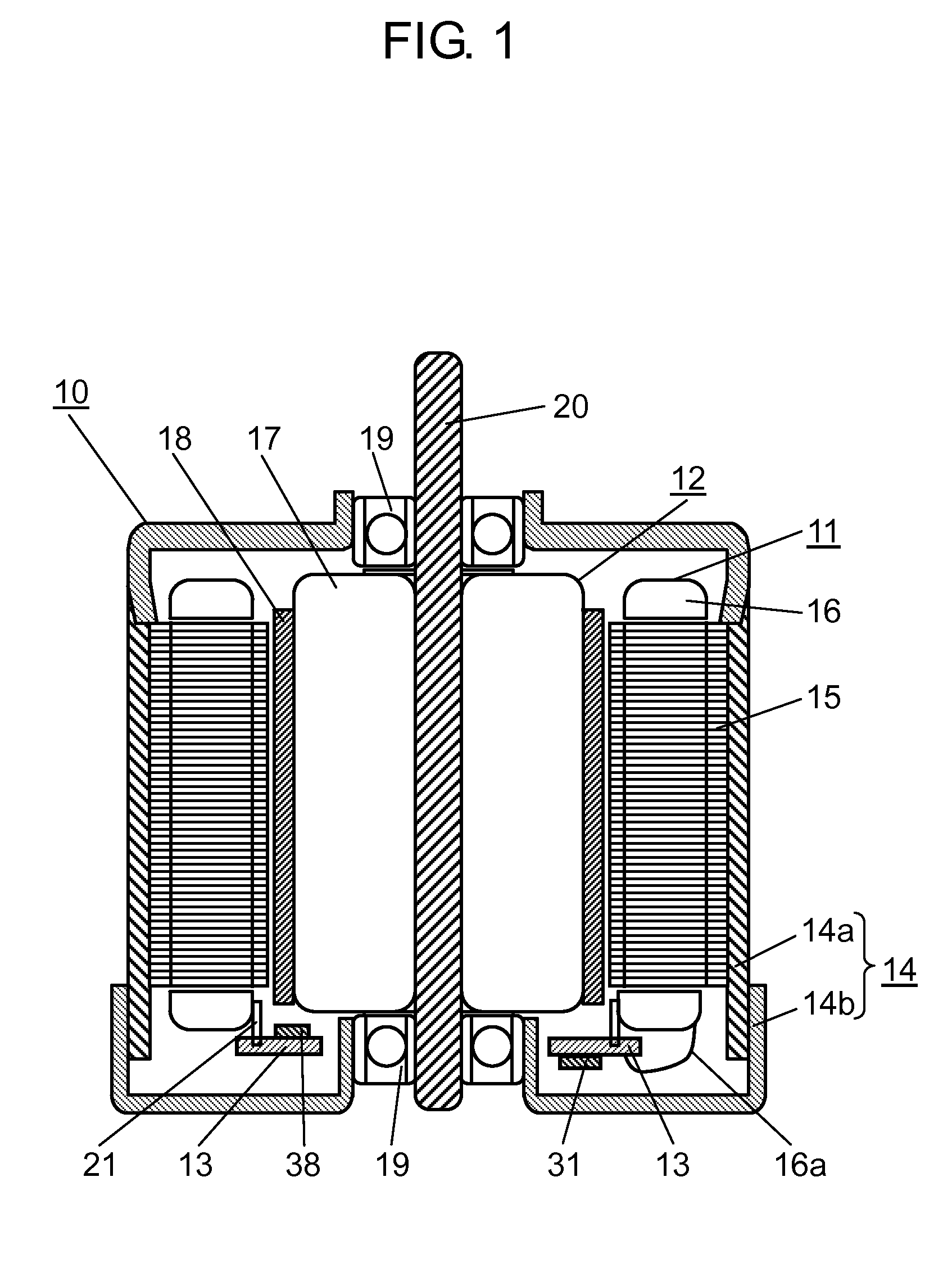
[0028]FIG. 1 is a view showing a structure of brushless motor 10 according to a first exemplary embodiment of the present invention. According to this exemplary embodiment, a description will be given of a case of an inner rotor type brushless motor in which a rotor is rotatably arranged on an inner periphery side of a stator. The brushless motor according to this exemplary embodiment has coils having a plurality of phases, and is rotationally driven by a signal which is pulse width modulated (hereinafter, referred to as PWM occasionally) for each phase.

[0029]As shown in FIG. 1, brushless motor 10 includes stator 11, rotor 12, circuit substrate 13, and motor case 14. Motor case 14 is made of metal formed into a sealed cylindrical shape, and brushless motor 10 is configured in such a manner that stator 11, rotor 12, and circuit substrate 13 are housed in motor case 14. Motor case 14 is composed of case body 14a and case lid 14b, and case lid 14b is mounted on case body 14a, whereby m...

second exemplary embodiment

[0068]FIG. 6 is a block diagram of motor drive device 60 according to a second exemplary embodiment. In this exemplary embodiment, similar to the first exemplary embodiment, motor drive device 60 is incorporated or integrated in brushless motor 10 shown in FIG. 1. Referring to FIG. 6, the same components as those in FIG. 2 are marked with the same reference marks, and their detailed description is omitted. Motor drive device 60 further includes timer 56 and cutoff control unit 57, compared with motor drive device 40 shown in FIG. 2.

[0069]Timer 56 receives overvoltage determined signal Vov from overvoltage determining unit 52. When it is determined to be the overvoltage in overvoltage determined signal Vov, timer 56 starts measuring a time from the determined time. While it is determined to be the overvoltage, timer 56 continues to measure the time from the time when it is determined to be the overvoltage for the first time until the present time so as to measure a period while it is...

third exemplary embodiment

[0083]FIG. 9 is a block diagram of motor drive device 80 in a third exemplary embodiment. Similar to the first and second exemplary embodiments, in this exemplary embodiment also, motor drive device 80 is incorporated or integrated in brushless motor 10 shown in FIG. 1. In FIG. 9, the same components as those in FIGS. 2 and 6 are marked with the same reference marks and their detailed description is omitted. Compared with the first exemplary embodiment, motor drive device 80 includes overvoltage determining unit 82 for determining the overvoltage in two stages, and further includes cutoff control unit 57 similar to the second exemplary embodiment.

[0084]Similar to the first exemplary embodiment, overvoltage determining unit 82 receives power supply voltage value Vt from voltage measuring unit 51. Overvoltage determining unit 82 determines whether or not power supply voltage Vcc is the overvoltage exceeding a first predetermined voltage and whether or not it is the overvoltage exceedi...


PUM


Abstract

A method for driving a motor including a stator wound with a coil and a rotor rotatably disposed and confronting the stator, whereby the coil is energized and driven at energizing timing of which phase is determined based on an advance angle amount to rotate the rotor. At this time, it is determined whether or not a power supply voltage supplied to the motor exceeds a predetermined voltage, and when it is determined that the power supply voltage exceeds the predetermined voltage, the advance angle amount is changed to increase a current amount flowing through the coil, for energizing and driving the coil.

Description

TECHNICAL FIELD[0001]The present invention relates to a motor drive method, a motor drive device, and a brushless motor for driving a motor in such a manner that when a power supply voltage increases and becomes an overvoltage because a large amount of noise is applied to a power supply line of the motor, they are prevented from being affected by the overvoltage.BACKGROUND ART[0002]As for a car, a mounted buttery serves as power supplies of mounted instruments. A vehicle mounts many instruments, and these instruments operate according to the situation while driving. Therefore, a power supply voltage of the mounted buttery considerably fluctuates compared with a power supply of a general electrical instrument. Furthermore, when the mounted buttery is cut off for some reasons while an engine is driven, it is known that a transient phenomenon called load dump is generated, and a high voltage is generated on a power supply line.[0003]Therefore, conventionally, there is a technique propo...

Claims


Application Information

Patent Timeline
Patent Type & Authority Patents(United States)
IPC IPC(8): H02P3/00H02P6/06H02P6/14
CPCH02P6/142H02P6/06H02P6/15
Inventor SATO, DAISUKE
Owner PANASONIC INTELLECTUAL PROPERTY MANAGEMENT CO LTD
Why Eureka
Try Eureka