Cut-mask patterning process for fin-like field effect transistor (FinFET) device

a technology of fin-like field effect transistor and patterning process, which is applied in the direction of photomechanical treatment originals, instruments, photomechanical equipment, etc., can solve the problems of limited device pattern formation, limited lithography resolution limits, and inability to meet the requirements of lithography resolution,

Active Publication Date: 2016-01-12
TAIWAN SEMICON MFG CO LTD
View PDF7 Cites 1648 Cited by
  • Summary
  • Abstract
  • Description
  • Claims
  • Application Information

AI Technical Summary

Problems solved by technology

Forming device patterns with smaller dimensions is limited by a resolution of the exposure tool.
For example, forming fin-like field effect (FinFET) devices is limited by current lithography resolution limits.
Accordingly, although existing lithography techniques have been generally adequate for their intended purposes, as device scaling down continues, they have not been entirely satisfactory in all respects.

Method used


Image

  • Cut-mask patterning process for fin-like field effect transistor (FinFET) device
  • Cut-mask patterning process for fin-like field effect transistor (FinFET) device
  • Cut-mask patterning process for fin-like field effect transistor (FinFET) device

Examples


Embodiment Construction

[0012]The following disclosure provides many different embodiments, or examples, for implementing different features of the invention. Specific examples of components and arrangements are described below to simplify the present disclosure. These are, of course, merely examples and are not intended to be limiting. For example, the formation of a first feature over or on a second feature in the description that follows may include embodiments in which the first and second features are formed in direct contact, and may also include embodiments in which additional features may be formed between the first and second features, such that the first and second features may not be in direct contact. In addition, the present disclosure may repeat reference numerals and / or letters in the various examples. This repetition is for the purpose of simplicity and clarity and does not in itself dictate a relationship between the various embodiments and / or configurations discussed. Furthermore, the pre...


PUM

PropertyMeasurementUnit
areaaaaaaaaaaa
densityaaaaaaaaaa
dimensionsaaaaaaaaaa

Abstract

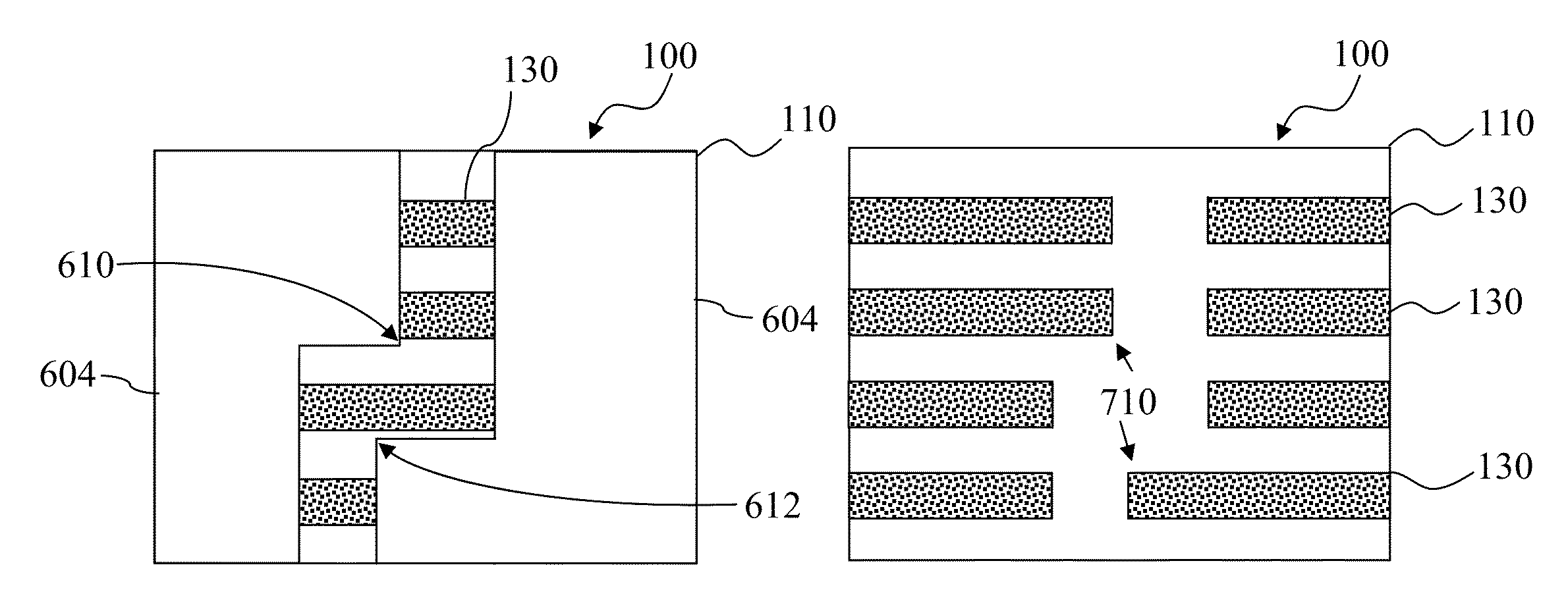
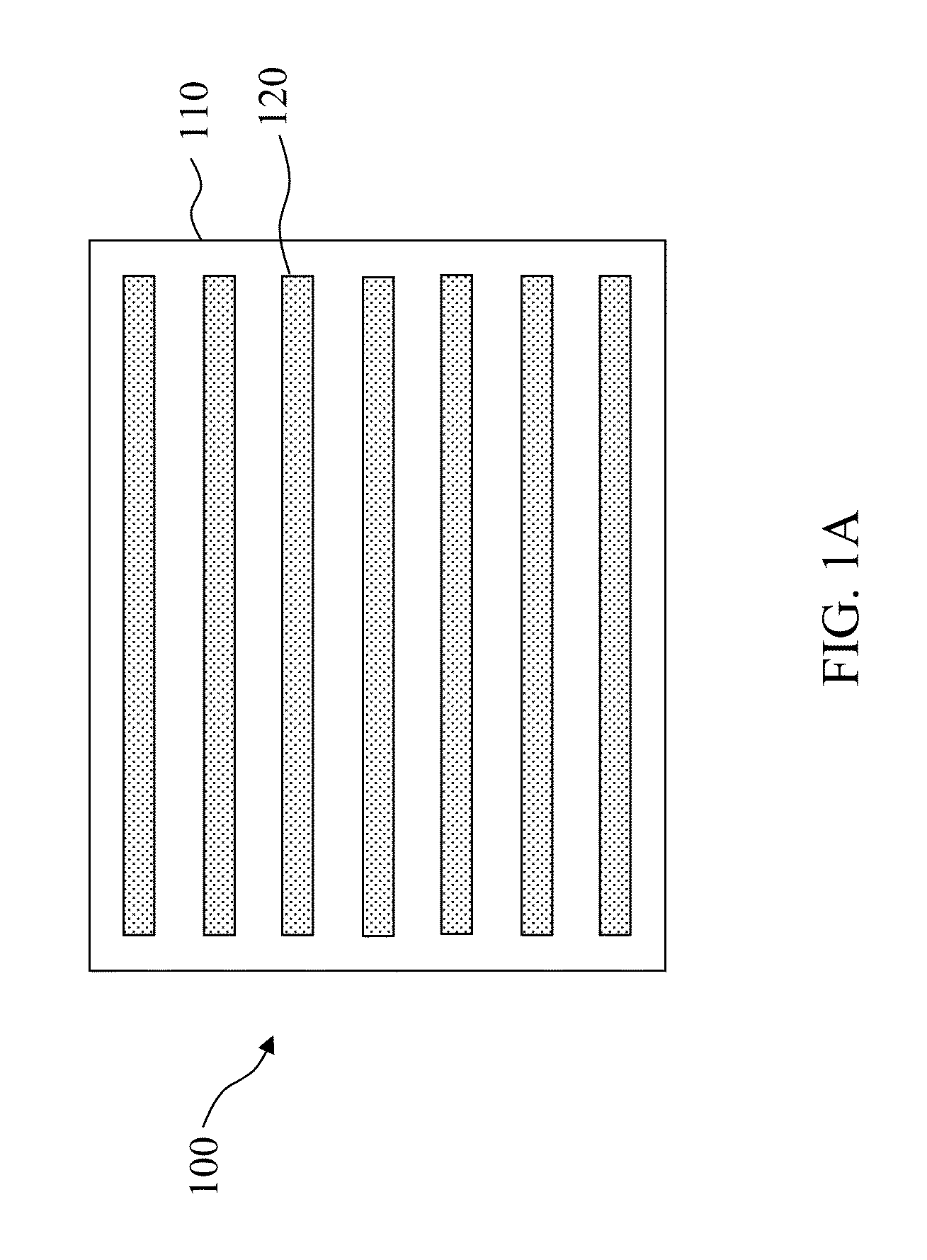
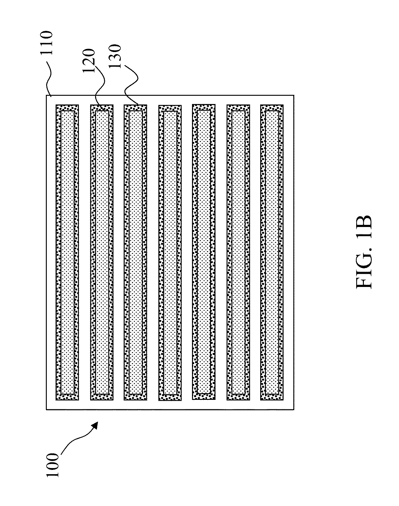
A method for patterning a plurality of features in a non-rectangular pattern, such as on an integrated circuit device, includes providing a substrate including a surface with a plurality of elongated protrusions, the elongated protrusions extending in a first direction. A first layer is formed above the surface and above the plurality of elongated protrusions, and patterned with an end cutting mask. The end cutting mask includes two nearly-adjacent patterns with a sub-resolution feature positioned and configured such that when the resulting pattern on the first layer includes the two nearly adjacent patterns and a connection there between. The method further includes cutting ends of the elongated protrusions using the pattern on the first layer.

Description

BACKGROUND[0001]Integrated circuit (IC) technologies are constantly being improved. Such improvements frequently involve scaling down device geometries to achieve lower fabrication costs, higher device integration density, higher speeds, and better performance. Lithography is frequently used for forming components of an integrated circuit device, where generally, an exposure tool passes light through a mask or reticle and focuses the light onto a resist layer of a wafer, resulting in the resist layer having an image of integrated circuit components therein. Forming device patterns with smaller dimensions is limited by a resolution of the exposure tool. For example, forming fin-like field effect (FinFET) devices is limited by current lithography resolution limits. Accordingly, although existing lithography techniques have been generally adequate for their intended purposes, as device scaling down continues, they have not been entirely satisfactory in all respects.SUMMARY[0002]The pre...

Claims


Application Information

Patent Timeline
Patent Type & Authority Patents(United States)
IPC IPC(8): H01L21/308H01L27/12H01L21/84
CPCH01L21/3086H01L21/3088H01L21/845H01L27/1211G03F7/70466G03F1/38
Inventor DE, HO WEILU, KUEI-LIANGSHIEH, MING-FENGCHANG, CHING-YU
Owner TAIWAN SEMICON MFG CO LTD
Why Eureka
Try Eureka