Electromotive furniture drive including a power supply device

a technology for electromotive furniture and power supply devices, applied in the direction of seating furniture, application, field or armature current control, etc., can solve the problems of mounting effort and cost, respectively high, and achieve the effect of simplifying the electromotive furniture drive and improving functionality

Inactive Publication Date: 2016-01-12
DEWERTOKIN GMBH
View PDF37 Cites 12 Cited by
  • Summary
  • Abstract
  • Description
  • Claims
  • Application Information

AI Technical Summary

Benefits of technology

[0008]The invention is based on the object of simplifying an electromotive furniture drive with a power supp...

Problems solved by technology

The costs are far from irrelevant however and the mounting effort is respectively high, sin...

Method used


Image

  • Electromotive furniture drive including a power supply device
  • Electromotive furniture drive including a power supply device
  • Electromotive furniture drive including a power supply device

Examples


first embodiment

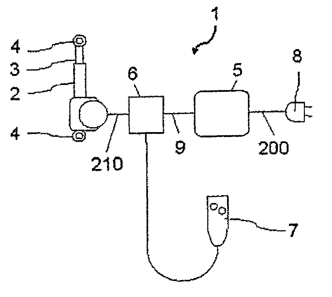
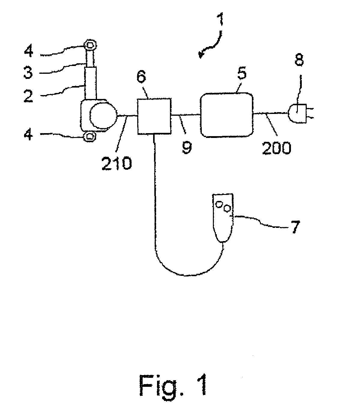
[0034]In accordance with the illustration of FIG. 1, the manual control 7 is connected to a motor controller 6 in a first embodiment, wherein the motor controller 6 is arranged as a relay controller with relay switches or / and as a semiconductor circuit with semiconductor switches. The pushbuttons of the manual control 7 which can be actuated manually switch the control current of the relay switches or semiconductor switches, wherein the power switches of the relay switches or the semiconductor switches switch the high motor current of the linear drive 2.

second embodiment

[0035]In accordance with the illustration of FIG. 1, the manual control 7 is connected to a motor controller 6 in a second embodiment, which connects a supply cable 9 of the power supply device 5 and a motor cable 210 of the electric motor of the linear drive 2 and the electric lines of the manually actuated pushbuttons of the manual control 7 to each other. In accordance with this embodiment, the contacts of the manually actuated pushbuttons of the manual control 7 are arranged as power switches and switch the high motor current upon pressing the buttons.

[0036]In a further developed embodiment, which is not shown in closer detail, the power supply device 5 is inserted into or attached to the housing of the linear drive 2, wherein the linear drive 2 can be arranged in the manner of a double drive (not shown in closer detail), which accommodates at least one motor, but preferably two motors, in a common housing.

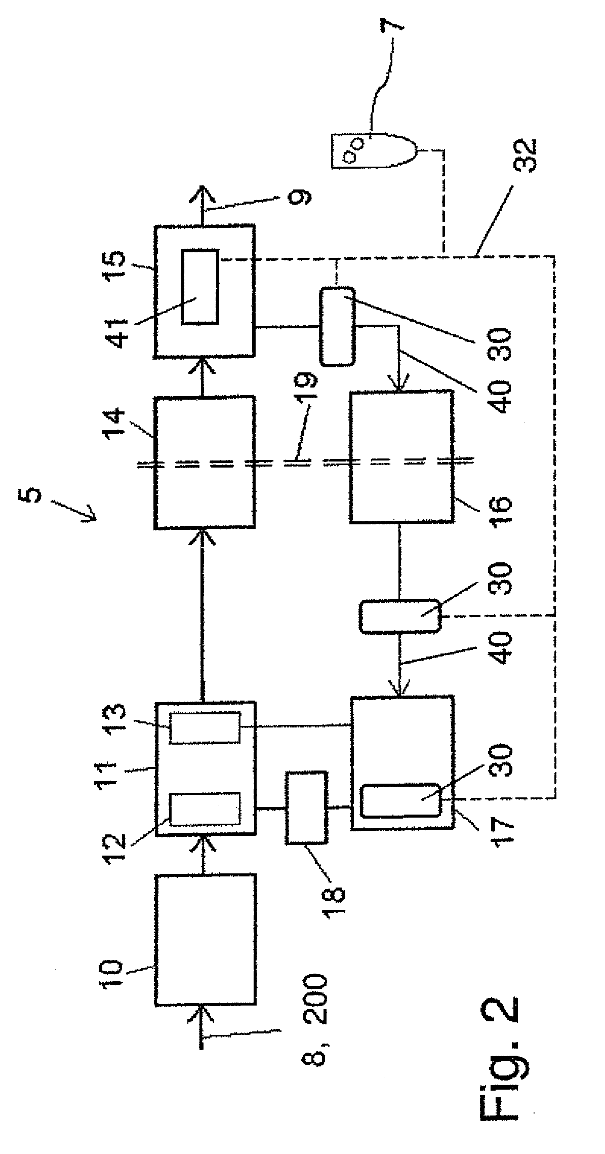
[0037]FIG. 2 shows a schematic block diagram of a first embodiment of the...


PUM


Abstract

An electromotive drive for furniture, includes a power supply device, a manual control, and a control device. The power supply device has an disconnecting unit that can be controlled by means of a control line, the electrical control signal of said control line being able to be modified by a switching contact of the manual control such that, when the manual control has not been actuated, the power supply device can be switched into the “disconnection” operating state, said disconnecting unit being connected to a signal feedback arrangement of a control circuit of the power supply device and being integrated in a path of said signal feedback arrangement, or said disconnecting unit being set in, or placed on, an input path or an output path of the control device.

Description

CROSS-REFERENCES TO RELATED APPLICATIONS[0001]This application is the U.S. National Stage of International Application No. PCT / EP2012 / 058218, filed May 4, 2012, which designated the United States and has been published as International Publication No. WO 2012 / 152681 and which claims the priority of German Patent Application, Serial No. 10 2011 050 194.0, filed May 6, 2011, pursuant to 35 U.S.C. 119(a)-(d).BACKGROUND OF THE INVENTION[0002]The invention relates to an electromotive furniture drive, comprising a power supply device for adjusting movable furniture components relative to one another.[0003]Such electromotive furniture drives are known in various embodiments. They are implemented as linear drives having a linearly adjustable output element or as rotational drives having a rotating output element and have proven themselves extremely well in practice. The linear drives have one or a number of electric motors, wherein a speed reduction gear is connected downstream of each moto...

Claims


Application Information

Patent Timeline
IPC IPC(8): H02P1/00A47C20/04H02P29/00A47C17/86H02P7/00H02H3/12A47B13/00A47B96/00A47C1/02H02P7/18
CPCH02P7/18A47B13/00A47B96/00A47C1/02A47C17/86A47C20/041H02H3/12H02P29/00
Inventor HILLE, ARMINMULLER, CHRISTIAN
Owner DEWERTOKIN GMBH
Why Eureka
Try Eureka