Incremented brake pipe pressure reduction

a technology of brake pipe and pressure reduction, which is applied in the direction of mechanical control devices, process and machine control, instruments, etc., can solve the problem that the operator cannot control the pressure of the brake pipe between the preconfigured, electronically controlled pneumatic (ecp) brake system

Active Publication Date: 2016-01-19
NEW YORK AIR BRAKE CORP
View PDF6 Cites 6 Cited by
  • Summary
  • Abstract
  • Description
  • Claims
  • Application Information

AI Technical Summary

Benefits of technology

[0006]The present invention comprises an incremental brake pipe reduction system that allows an operator to create an equalizing reservoir (ER) target value without having to manually move the handle to an imprecise position. By using a pushbutton, a switch, or a touchscreen on the man-machine brake control interface or through an input or communication message to the brake system from another HMI device such as a button or operator display screen on the locomotive, the operator can request incremental reductions in brake pressure to more accurately select the desired level of braking. For example, once an operator has requested a ‘minimum’ brake application, the operator may then reduce brake pipe pressure in small, predetermined increments to provide for more precise control over brake pressure without having to move the brake handle to a position that the operator guesses will accomplish the desired decrease in desired brake pressure. Optionally, an amount of BP reduction within the service zone between ‘minimum’ and ‘full service’ could also be enabled to allow for this incremental reduction to occur.

Problems solved by technology

While control levers are good at giving the operator quick intuitive control of the brake level, they do not allow an operator to control the brake pipe (BP) pressure between the preconfigured ‘set’ positions as precisely as they desire in some situations.
Another issue with conventional braking systems is that the locomotive operators making reductions in brake pipe pressure must often prevent the locomotives brakes from applying by using a bail off feature due to operating rules or the conditions of train control.
These same issues exist in electronically controlled pneumatic (ECP) brake systems.

Method used


Image

  • Incremented brake pipe pressure reduction
  • Incremented brake pipe pressure reduction
  • Incremented brake pipe pressure reduction

Examples


Embodiment Construction

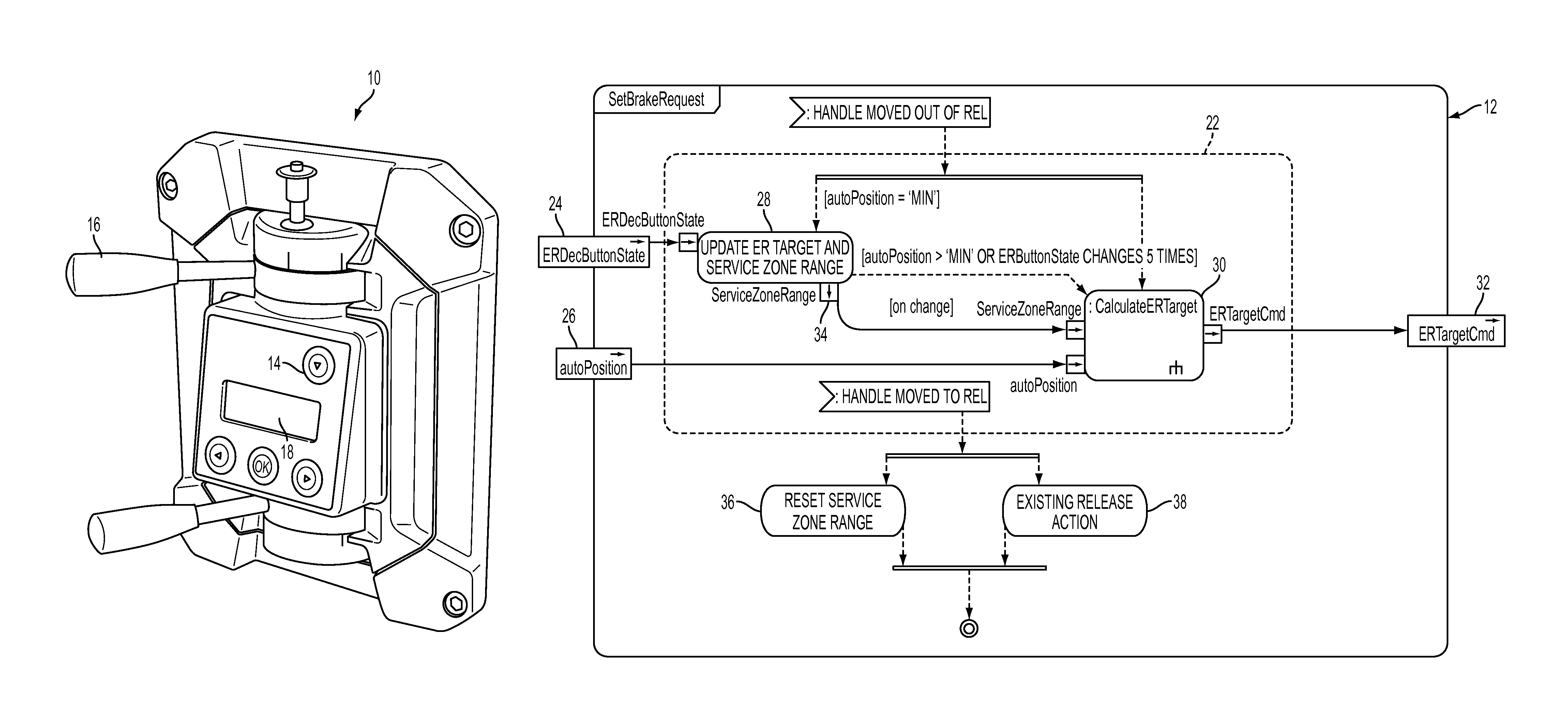
[0012]Referring now to the drawings, wherein like reference numerals refer to like parts throughout, there is seen in FIG. 1 a brake controller 10 including a system 12 for incrementally adjusting brake pressure. As seen in FIG. 1, system 12 is made available to an operator by a single button 14 that allows operator to incrementally reduce brake pressure without having to move brake handle 16. It should be recognized by those of skill in the art that button 14 may instead comprise a switch, a touchscreen, or a combination thereof on brake controller 10, and that incremental reductions may be accomplished by depressing button 14 a series of times to accomplish a series of individual, predetermined reductions or holding button 14 down while a keystroke buffer gradually and periodically cycles through a series of incremental reductions until the appropriate level is reached and the operator releases button 14. A display 18 may also be provided to show the operator the specific brake pr...


PUM


Abstract

A system and method for incrementally accomplishing brake pipe reductions using an operator button, touch sensitive screen or other human machine interface. The system is preferably made available to the user when the brake handle is positioned in the ‘minimum’ brake application position and allows an operator to create a more precise target reduction value without having to manually move the brake handle to the location that the operator believes may result in the desired reduction. Using small, predetermined increments, the system allows for more precise control over brake pressure without an operator having to estimate what handle movement will accomplish the desired brake pressure.

Description

BACKGROUND OF THE INVENTION[0001]1. Field of the Invention[0002]The present invention relates to locomotive braking systems and, more particularly, to a system and method for incrementally reducing brake pipe pressure.[0003]2. Description of the Related Art[0004]Locomotive operators using pneumatic or electro-pneumatic braking systems are often required to make minor reductions in brake pipe pressure beyond the minimum braking level when grade braking or in other situations. Brake control levers positioned on a locomotive mounted brake controller are used as the man machine interface for brake pipe control. These levers typically have set positions for a defined reduction of equalizing reservoir (ER) pressure, which is the pilot pressure for the brake pipe relay and thus provides the target level for the brake pipe (BP) pressure. For example, the handle position typically labelled ‘minimum’ allows for the minimum amount of brake which can be applied, while the position referred to a...

Claims


Application Information

Patent Timeline
Patent Type & Authority Patents(United States)
IPC IPC(8): B60T13/66B60T7/08B60T15/00B61H13/02B61H13/00
CPCB61H13/02B60T7/085B60T13/662B60T13/665B61H13/00B60T13/683B60T15/048B60T17/228G05G1/015
Inventor LEONARD, ERICHREYNOLDS, JOHN
Owner NEW YORK AIR BRAKE CORP
Why Eureka
Try Eureka