Solar cell including microlens and method of fabricating the same

a microlens and solar cell technology, applied in the field of solar cells, can solve the problems of high fabrication cost, complicated steps, and expensive photo masks for the exposure step, and achieve the effects of simple and accurate formation, improved light collection efficiency, and improved fabrication time and effect of tim

Active Publication Date: 2016-01-19
LG DISPLAY CO LTD
View PDF10 Cites 0 Cited by
  • Summary
  • Abstract
  • Description
  • Claims
  • Application Information

AI Technical Summary

Benefits of technology

[0011]An advantage of the present invention is to provide a method of fabricating a solar cell including a microlens where the microlens is simply and accurately formed and a fabrication time and a fabrication cost are reduced.
[0012]Another advantage of the present invention is to provide a solar cell including a microlens as a light collecting means where a light collecting efficiency is improved and a fabrication cost is reduced.

Problems solved by technology

Specifically, the exposure step requires an expensive photo mask and an expensive exposure apparatus.
As a result, a microlens according to the related art is fabricated through complicated steps with a high fabrication cost.

Method used


Image

  • Solar cell including microlens and method of fabricating the same
  • Solar cell including microlens and method of fabricating the same
  • Solar cell including microlens and method of fabricating the same

Examples


Embodiment Construction

[0027]Reference will now be made in detail to embodiments of the present invention, examples of which are illustrated in the accompanying drawings. Wherever possible, similar reference numbers will be used to refer to the same or similar parts.

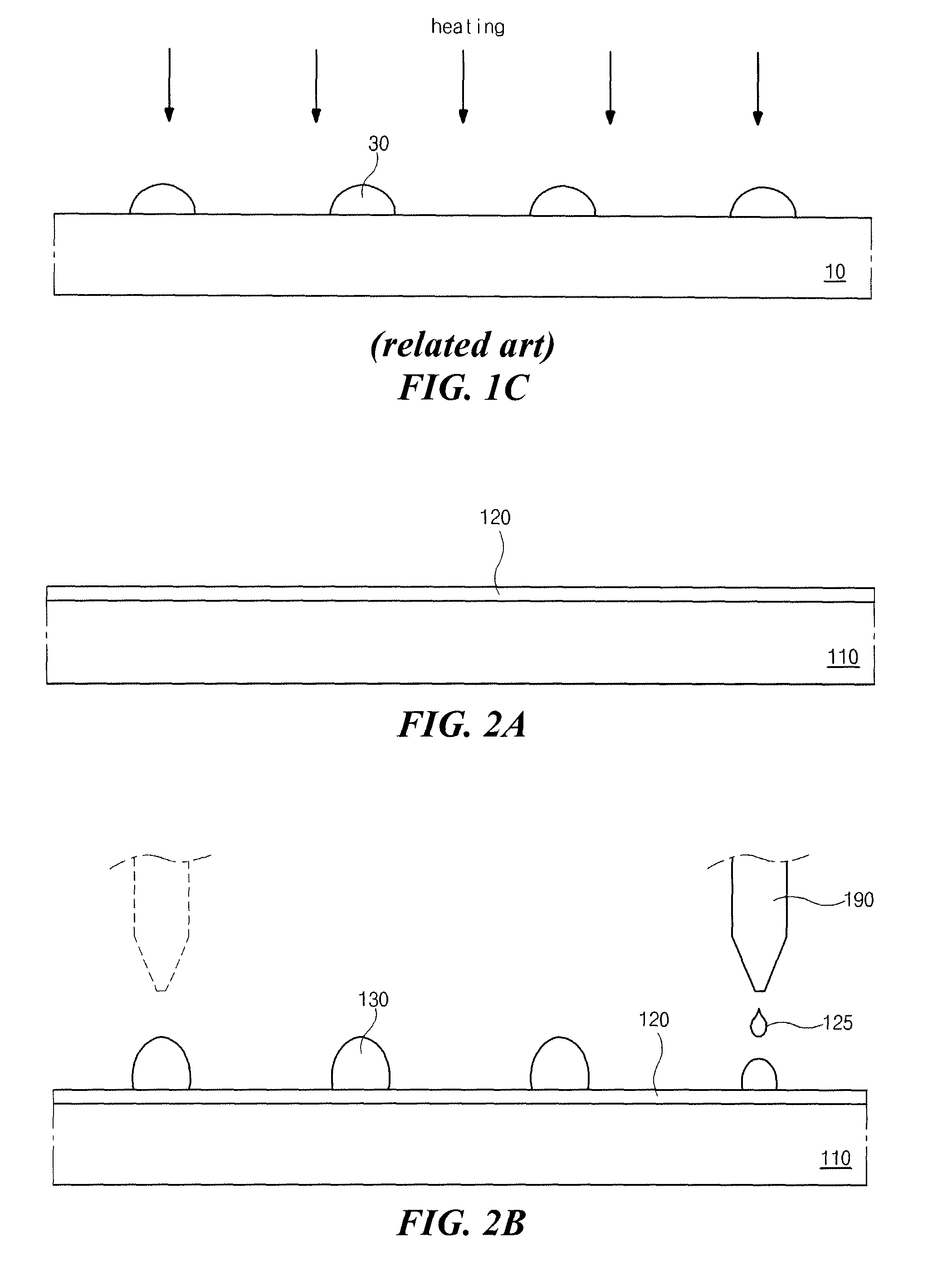
[0028]FIGS. 2A to 2C are cross-sectional views showing a method of fabricating a microlens according to an embodiment of the present invention, and FIG. 3 is a view showing a basic structure of a self assembly monolayer for a microlens according an embodiment of the present invention. In addition, FIG. 4 is a picture showing an ink droplet for a microlens according to an embodiment of the present invention and FIG. 5 is a graph showing a cross-sectional profile posterior to a drying step of an ink droplet including first and second solvents having first and second boiling points, respectively, different from each other for a microlens according to an embodiment of the present invention.

[0029]In FIG. 2A, a self assembly monolayer (SAM) 120 havi...


PUM


Abstract

Disclosed is a method of fabricating a microlens. The method includes forming a self assembly monolayer having a strong hydrophobicity on a substrate; forming a plurality of ink droplets on the self assembly monolayer by jetting a transparent ink using an inkjet apparatus, the transparent ink including a first solvent having a first boiling point, a second solvent having a second boiling point lower than the first boiling point and a silicon oxide (SiOx) solid material dispersed in the first and second solvents; and drying the plurality of ink droplets.

Description

[0001]This application claims the benefit of Korean Patent Application No. 10-2010-0039076, filed on Apr. 27, 2010, which is hereby incorporated by reference in its entirety.BACKGROUND OF THE INVENTION[0002]1. Field of the Invention[0003]The present invention relates to a solar cell, and more particularly, to a solar cell including a microlens for improving light capture property and a method of fabricating the solar cell.[0004]2. Discussion of the Related Art[0005]In general, a solar cell, which is a semiconductor device converting a solar energy into an electric energy, includes a junction of a positive (P) type semiconductor and a negative (N) type semiconductor and has the same basic structure as a diode. Most typical solar cells have a structure of a positive-negative (PN) junction semiconductor layer where a P type semiconductor layer and an N type semiconductor layer between facing two electrodes.[0006]For the purpose of improving photoelectric efficiency, the solar cell incl...

Claims


Application Information

Patent Timeline
Patent Type & Authority Patents(United States)
IPC IPC(8): H01L31/00H02S40/22G02B3/00H01L31/054H01L31/056H01L31/075
CPCG02B3/0056H01L31/0543H02S40/22H01L31/075Y02E10/52Y02E10/548H01L31/056
Inventor KIM, JAE-HYUNPARK, SEONG-KEELIM, JUNG-SHIKLEE, TAE-YOUNGKIM, MIN-CHEOL
Owner LG DISPLAY CO LTD
Why Eureka
Try Eureka