
Decoupled drive unit for a loudspeaker enclosure

a drive unit and enclosure technology, applied in the field of loudspeakers, can solve the problems of loss and/or distortion of acoustic output, inability to make the cabinet radiate as a rigid body, and inability to achieve the effect of ensuring the performance of the loudspeaker unit, ensuring the effect of good balance and matching

Active Publication Date: 2016-01-19
B & W GRP LTD
View PDF17 Cites 3 Cited by
  • Summary
  • Abstract
  • Description
  • Claims
  • Application Information

AI Technical Summary

Benefits of technology

The present invention is about a new way to design decoupled drive units for loudspeakers. Unlike previous proposals, this invention both decouples the magnet from the enclosure and ensures that the diaphragm acts against a volume of air during its movement. This arrangement helps to better control the sympathetic vibration of the magnet, either for increasing output levels or reducing its impact on sound quality. In some cases, the second volume, which is usually vented to the outside of the enclosure, may be vented to the front or rear of the enclosure. This helps to dampen down the air spring effect of the second volume. The surface to which the magnet is coupled should be comparable in size to the diaphragm surface area. This helps to balance and match the forces acting on the magnet and the diaphragm. Overall, this invention provides better control over the sound output and quality of the loudspeowned.

Problems solved by technology

It is not practical to make the cabinet radiate as a rigid body, so resonances are common.
This output is generally seen to be undesirable and many steps are taken to reduce it.
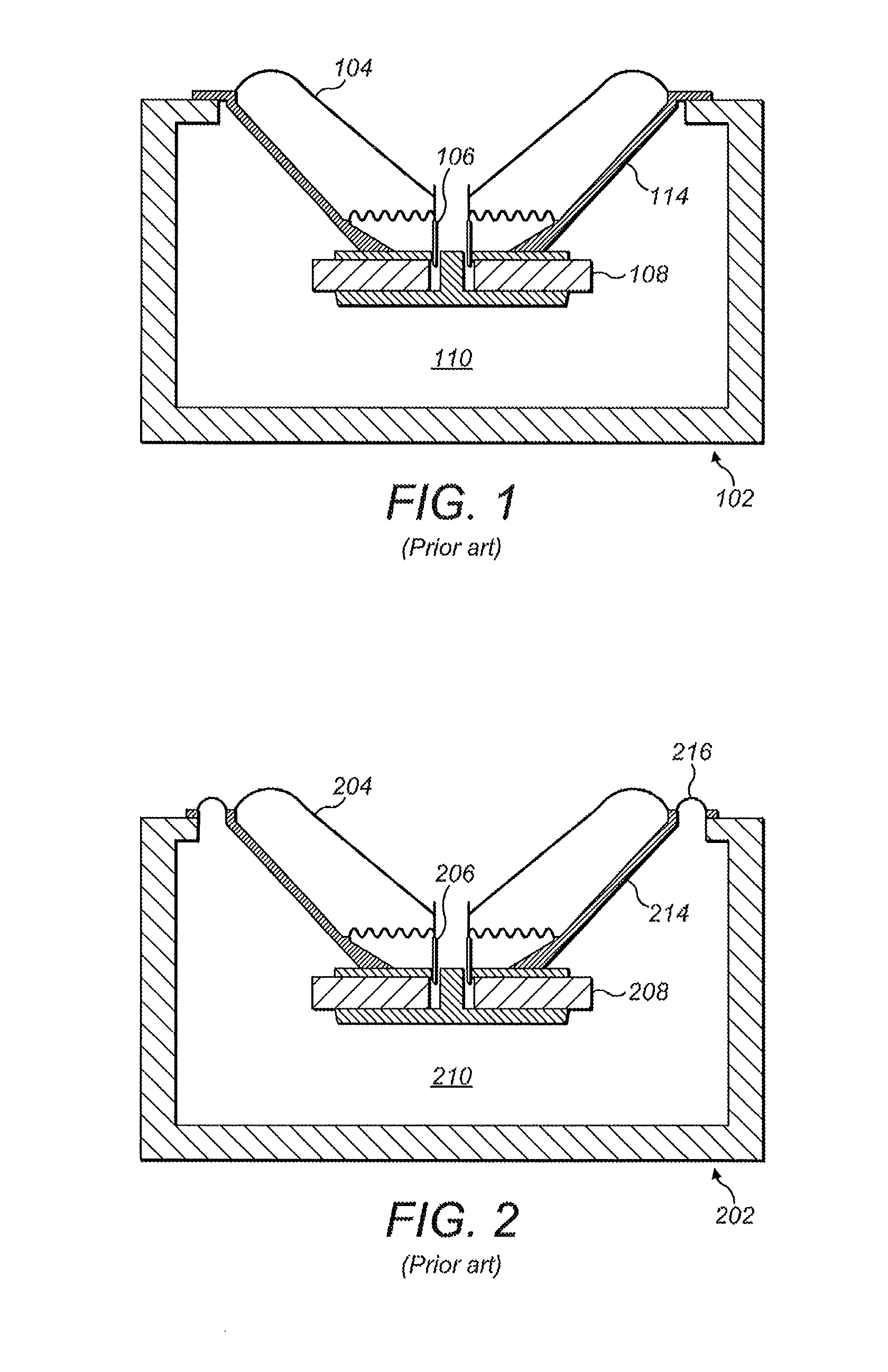
If the air spring's stiffness is significant, relative to the resilience of the mounting, then the magnet 208 will move in addition to or even in preference to the diaphragm 204, resulting in a loss of and / or distortion in acoustic output.

Method used


Image

  • Decoupled drive unit for a loudspeaker enclosure
  • Decoupled drive unit for a loudspeaker enclosure
  • Decoupled drive unit for a loudspeaker enclosure

Examples


first embodiment

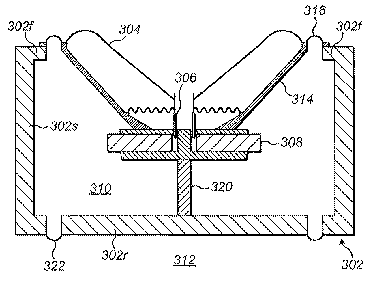
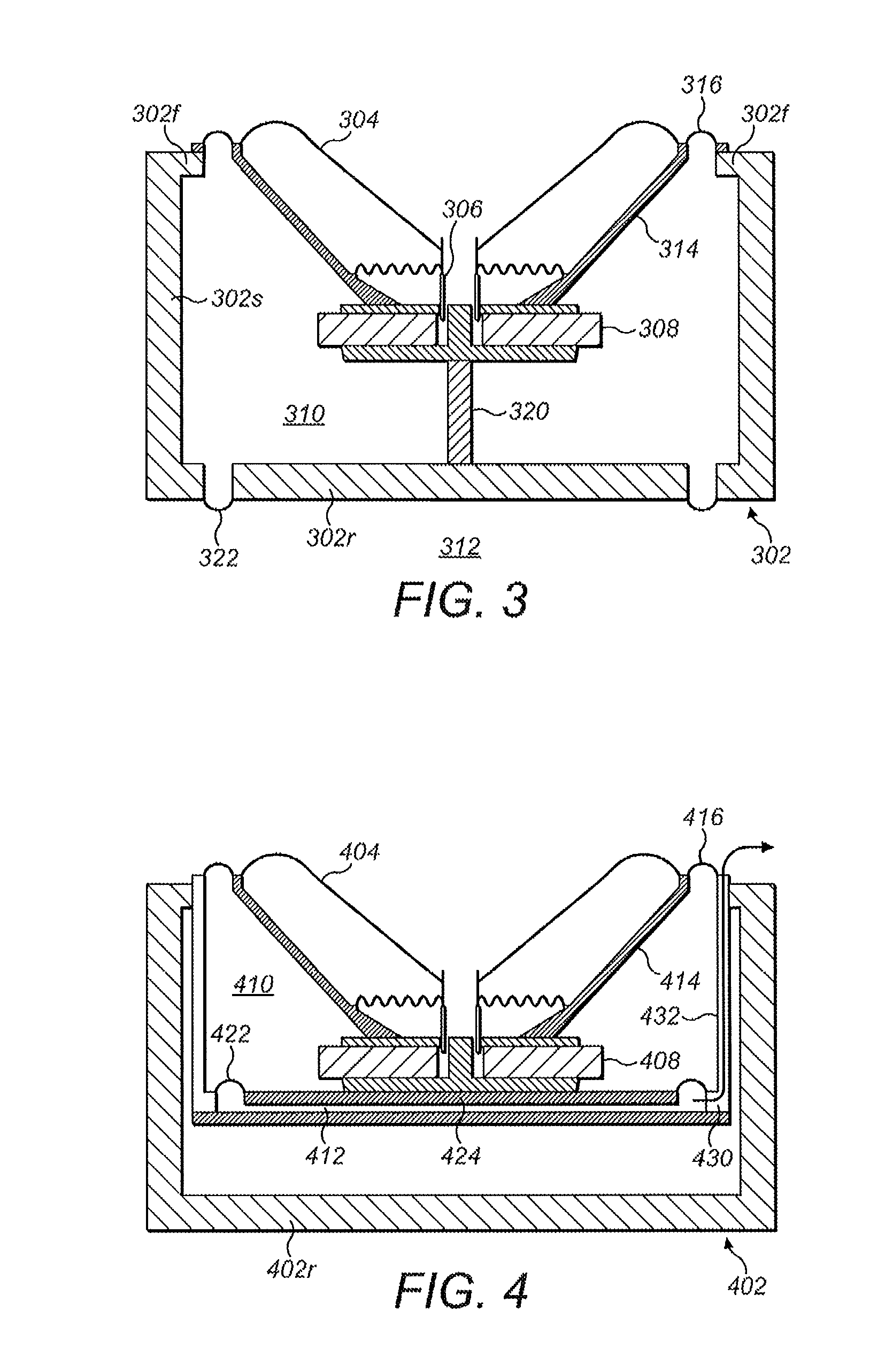
[0035]A balanced decoupled loudspeaker cabinet 302 is shown in FIG. 3. The exterior of the generally cuboidal cabinet 302 is formed by six panels including side panels 302s, a rear panel 302r and a front panel 302f. The loudspeaker cabinet 302 includes a mid-bass drive unit, which comprises a diaphragm 304 driven by a coil 306 reacting against a field produced by a magnet 308. The coil 306 vibrates the diaphragm 304 in sympathy with an applied electrical signal to create a sound. Sound radiates from the diaphragm forwardly through the aperture in the front panel 302f of the cabinet 302. The magnet 308 is housed in a chassis 314 that is physically connected to, but vibrationally decoupled from, the front panel 302f by means of a resilient mounting 316, in the form of a silicone ring. The magnet 308 is therefore effectively decoupled from the cabinet 302.

[0036]A first volume 310 in the cabinet 302 acts as an air spring such that, on application of an appropriate electrical signal to ...

fifth embodiment

[0042]FIG. 7 shows a loudspeaker cabinet 602 according to a In this embodiment, the loudspeaker drive unit comprising the first chassis 614, magnet 608, coil 606 and diaphragm 604 are arranged in inverted formation and the enclosure 602 is designed for installation in a cavity in a wall of a building, for example a house, cinema, recording studio or the like. The first chassis 614 has a open structure defined by four legs 614l extending inwardly from an annular ring structure 614r. The diaphragm 604 is positioned rearwardly of the legs and sound radiates though the open regions between the legs 614l. The first chassis 614 holds the magnet 608 and is also connected to and coupled with an interior panel 624. The second chassis 630 is coupled and connected to the front of the cabinet by means of a conventional bond. The legs of the second chassis 630 are hollow and define vents 632 for venting air to and from the second volume 612. The first chassis 614 is connected to the second chas...


PUM


Abstract

A loudspeaker enclosure defined by one or more panels housing a drive unit. The drive unit includes a coil, a diaphragm, and a magnet. The magnet is decoupled from the one or more panels of the loudspeaker enclosure. Sound is generated by the movement of the diaphragm and complementary movement of the magnet, on application of an appropriate electrical signal to the coil. The moving diaphragm acts against a first volume of air within the enclosure, while the movement of a surface coupled to the magnet, acts against a second air volume, different from the first volume. The surface coupled to the magnet is decoupled from the one or more panels of the loudspeaker enclosure.

Description

BACKGROUND OF THE INVENTION[0001]The present invention concerns loudspeakers. More particularly, but not exclusively, this invention concerns a loudspeaker enclosure housing a decoupled drive unit for a loudspeaker enclosure.[0002]A conventional moving coil loudspeaker cabinet 102 is shown in FIG. 1. This utilises a diaphragm 104 driven by a coil 106 reacting against a field produced by a magnet 108. The coil 106 vibrates the diaphragm 104 in sympathy with an applied electrical signal to create a sound. The out of phase sound emanating from the rear of the diaphragm 104 that would otherwise interfere with this sound is trapped inside the volume interior 110 of the cabinet 102. This volume 110 acts as an air spring that resists the motion of the diaphragm 104. To counteract this force the magnet 108 may be rigidly held by a chassis 114 which fixes the loudspeaker in the cabinet. The chassis 114 consists of legs or a perforated cone, allowing the diaphragm 104 to radiate sound into th...

Claims


Application Information

Patent Timeline
Patent Type & Authority Patents(United States)
IPC IPC(8): H04R1/28H04R1/02H04R15/00
CPCH04R1/02H04R1/2896H04R15/00H04R1/025H04R1/2815H04R2207/00H04R2217/00H04R1/2803H04R1/2811H04R9/02H04R9/06H04R2400/07H04R2201/021
Inventor NEVILL, STUART, MICHAEL
Owner B & W GRP LTD
Learn More