Fibre optic distributed sensing

a technology of distributed sensing and fibre optic cables, applied in the direction of converting sensor output, material analysis by observing immersed bodies, instruments, etc., can solve the problem that the use of standard telecommunications fibre optic cables may not provide optimal sensing, and achieve the effect of increasing the operating range, increasing the optical power, and enhancing the non-linear optical power threshold

Active Publication Date: 2016-01-26
OPTASENSE HLDG LTD
View PDF11 Cites 14 Cited by
  • Summary
  • Abstract
  • Description
  • Claims
  • Application Information

AI Technical Summary

Benefits of technology

[0020]If the fibre exhibits a significant difference in sensitivity to incident acoustic signals from different direction the fibre will exhibit directional sensitivity. Directional sensitivity in a DAS sensor can be very advantageous in locating the source of acoustic signals and / or identifying the different components of an acoustic signal such as a seismic signal.
[0021]As mentioned the microstructured fibre may have either a solid core or a hollow core depending on the arrangement. However in some embodiments a hollow core microstructured fibre such as a photonic band gap fibre may be configured to provide an enhance non-linear optical power threshold which can be advantageous.
[0022]In fibre optic distributed acoustic sensors where the fibre is interrogated with pulses of radiation and radiation which is Rayleigh backscattered is detected is it typically necessary to avoid certain non-linear effects within the fibre. One such non-linear effect is modulation instability. Another non-linear effect is stimulated Brillouin scattering.
[0023]In hollow core fibres the core will generally fill with air (unless deliberately filled with some other gas). The skilled person will appreciate that the power thresholds for non-linear effects may be higher for transmission through air than for transmission through solid core material. Thus optical pulses of greater optical power, i.e. greater intensity, may be used in an air core waveguide than with a solid core waveguide without experiencing unwanted non-linear effects. This is advantageous as the effective length of fibre which can be monitored by a distributed acoustic sensor is partly dependent on the intensity of the interrogating pulse and increasing the intensity increases the operating range.
[0024]In another aspect of the present invention there is provided a method of distributed acoustic sensing comprising, launching at least one pulse of optical radiation into an optical fibre and detecting radiation backscattered from within the fibre wherein the optical fibre is a microstructured optical fibre configured to provide at least one of an enhanced sensitivity to a given incident acoustic signal; an enhanced non-linear optical power threshold and directional sensitivity.

Problems solved by technology

In some instances though the use of standard telecommunications fibre optic cable may not provide optimal sensing.

Method used


Image

  • Fibre optic distributed sensing
  • Fibre optic distributed sensing

Examples


Embodiment Construction

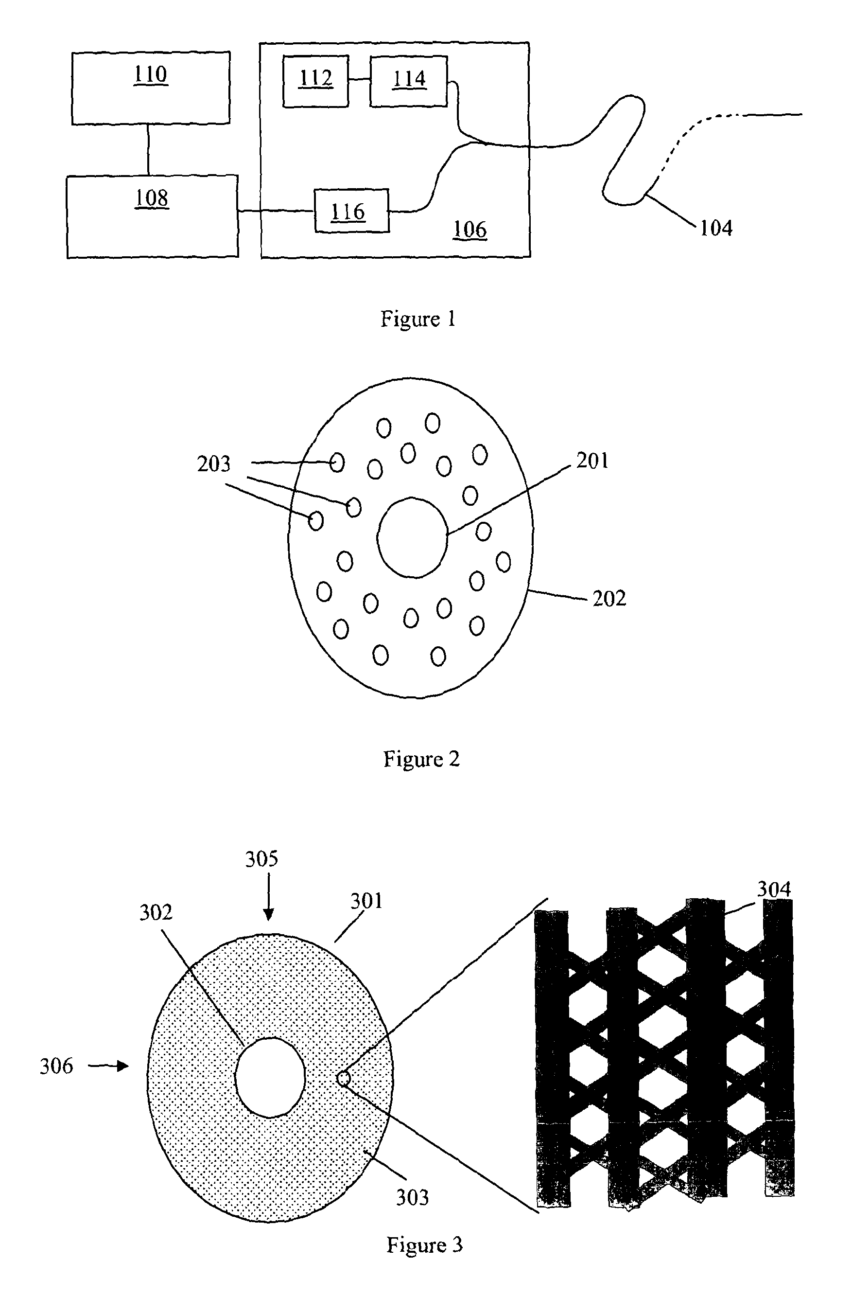
[0033]FIG. 1 shows a schematic of a fibre optic distributed acoustic sensing (DAS) arrangement. A length of sensing fibre 104 is connected at one end to an interrogator 106. The output from interrogator 106 is passed to a signal processor 108, which may be co-located with the interrogator or may be remote therefrom, and optionally a user interface / graphical display 110, which in practice may be realised by an appropriately specified PC. The user interface may be co-located with the signal processor or may be remote therefrom.

[0034]The sensing fibre 104 can be many kilometers in length, for example it may be approximately 40 km long. In conventional applications of optical fibre distributed sensors the sensing fibre is at least partly contained within a medium which it is wished to monitor. For example, the fibre 104 may be buried in the ground to provide monitoring of a perimeter or monitoring of a buried asset such as a pipeline or the like.

[0035]In operation the interrogator 106 l...


PUM


Abstract

This application describes methods and apparatus for fiber optic distributed acoustic sensing (DAS) where microstructured fiber (202), such as holey fiber or photonic crystal fiber is used as the sensing fiber (104). The microstructured fiber is configured so to provide at least one of enhanced sensitivity to a given incident acoustic signal; an enhanced non-linear optical power threshold and directional sensitivity. By configuring the microstructured fiber to be more compliant than an equivalent solid fiber and/or provide a large refractive index variation in response to applied strain, the response to a given acoustic stimulus may be larger than for the equivalent fiber, Providing a hollow core may allow higher optical powers and by providing a directionality to microstructured (304) allows the fiber to be used in a DAS system with a directional response.

Description

FIELD OF THE INVENTION[0001]The present invention relates to fibre optic distributed sensing and in particular to fibre optic distributed sensors such as distributed acoustic sensors in which a sensing fibre is interrogated with pulses of radiation. The invention also relates to optical fibres and fibre optic cables suitable for use in fibre optic distributed sensing.BACKGROUND OF THE INVENTION[0002]Various sensors utilizing optical fibres are known. Many such sensors rely on fibre optic point sensors or discrete reflection sites such as fibre Bragg gratings or the like being arranged along the length of an optical fibre. The returns from the discrete point sensors or reflection sites can be analysed to provide an indication of the temperature, strain and / or vibration in the vicinity of the discrete sensors or reflection sites.[0003]Fully distributed fibre optic sensors are also known in which the intrinsic scattering from a continuous length of optical fibre is used. Such sensors a...

Claims


Application Information

Patent Timeline
Patent Type & Authority Patents(United States)
IPC IPC(8): G02B6/00G01J1/42G02B6/32G02B6/02G01D5/353G01H9/00G02B6/032
CPCG01H9/00G01D5/353G01H9/004G02B6/00
Inventor CRICKMORE, ROGER IANGODFREY, ALASTAIR
Owner OPTASENSE HLDG LTD
Why Eureka
Try Eureka