Ion trap device

a technology of ion traps and ion traps, which is applied in the direction of particle separator tubes, particle separator tubes, electric discharge tubes, etc., can solve the problem that the meshes do not efficiently store ions at high pressur

Active Publication Date: 2016-01-26
BATTELLE MEMORIAL INST
View PDF9 Cites 12 Cited by
  • Summary
  • Abstract
  • Description
  • Claims
  • Application Information

AI Technical Summary

Problems solved by technology

However, these meshes do not store ions efficiently at high pressure.

Method used


Image

  • Ion trap device
  • Ion trap device
  • Ion trap device

Examples


Embodiment Construction

[0033]The present invention relates to methods, devices, and apparatuses for selectively trapping and releasing ions. In certain embodiments, a voltage is applied to a series or set of concentric ring electrodes—without the use of meshes—to selectively trap and release ions traveling through the rings. The voltage applied to the electrodes to repel the ions may be a RF field or a DC field. These gridless gate devices can release ions from a trap and achieve high sensitivity by reducing losses into the grids. The present invention also works efficiently at high pressures (>50 mtorr).

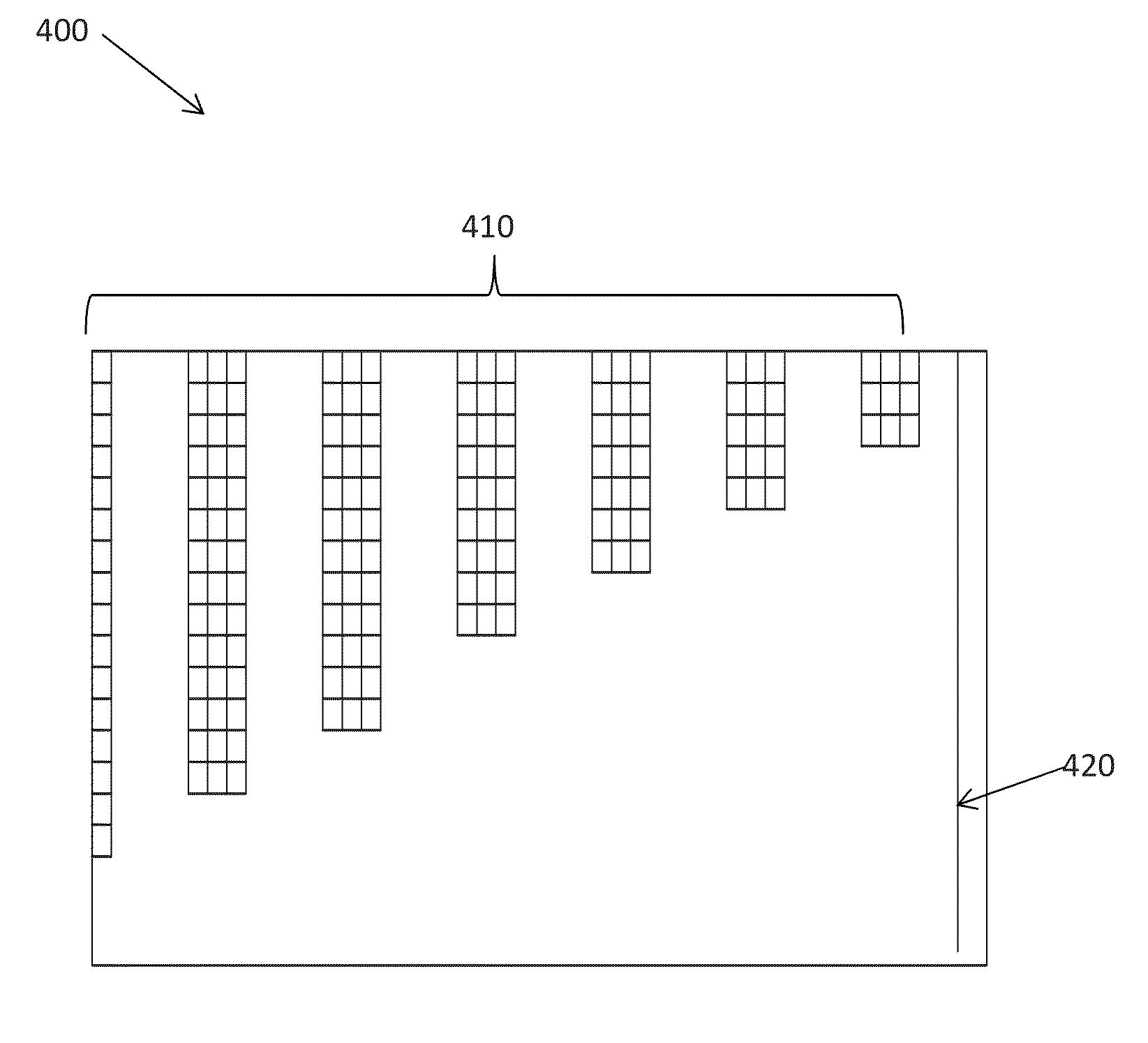
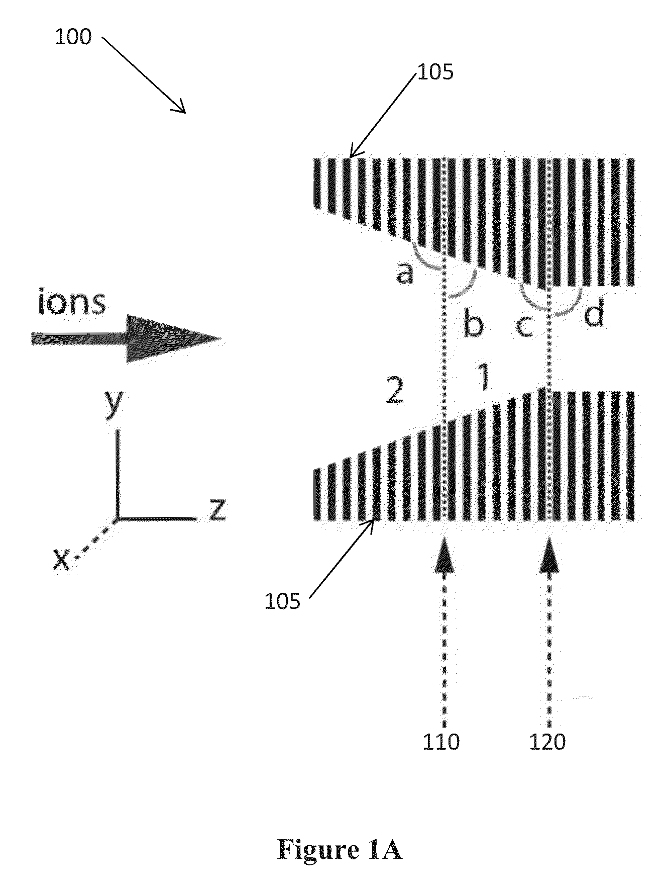
[0034]FIG. 1A is a schematic of an ion trap device 100, in accordance with one embodiment of the present invention. The device 100 includes a series of electrodes 105, an entrance grid 110, and an exit grid 120. Ions are transmitted through an opening of the electrodes 105 toward the middle of the device 100. The electrodes 105 may be ring electrodes, and the ring electrodes may be assembled in stacks.

[00...


PUM


Abstract

An ion trap device is disclosed. The device includes a series of electrodes that define an ion flow path. A radio frequency (RF) field is applied to the series of electrodes such that each electrode is phase shifted approximately 180 degrees from an adjacent electrode. A DC voltage is superimposed with the RF field to create a DC gradient to drive ions in the direction of the gradient. A second RF field or DC voltage is applied to selectively trap and release the ions from the device. Further, the device may be gridless and utilized at high pressure.

Description

CROSS REFERENCE TO RELATED APPLICATIONS[0001]The application claims priority to U.S. Provisional Application Ser. No. 61 / 779,825, filed Mar. 13, 2013, entitled “ION TRAPS AND PROCESS,” hereby incorporated by reference for all of its teachings.STATEMENT REGARDING FEDERALLY SPONSORED RESEARCH OR DEVELOPMENT[0002]This invention was made with Government support under Contract DE-AC05-76RLO1830 awarded by the U.S. Department of Energy and Grant No. R21 GM103497 awarded by the National Institutes of Health. The Government has certain rights in the invention.TECHNICAL FIELD[0003]This invention relates to ion traps. More specifically, this invention relates to a gridless ion trap device that selectively traps and releases ions at high pressure by applying voltage to electrodes.BACKGROUND OF THE INVENTION[0004]Ion traps known in the art apply a DC potential to metal grids that create a repelling potential which prevent ions from moving into or out of the trap. However, these meshes do not st...

Claims


Application Information

Patent Timeline
Patent Type & Authority Patents(United States)
IPC IPC(8): H01J49/34H01J49/06
CPCH01J49/065
Inventor IBRAHIM, YEHIA M.SMITH, RICHARD D.
Owner BATTELLE MEMORIAL INST
Why Eureka
Try Eureka