Intensity modulated three-dimensional radiation scanning method and apparatus

a three-dimensional radiation and intensity modulation technology, applied in the field of solid cancer treatment, can solve the problems of reducing the ability to repair damaged dna, affecting the detection accuracy of cancer cells,

Active Publication Date: 2013-10-29
BALAKIN ANDREY VLADIMIROVICH +1
View PDF369 Cites 49 Cited by
  • Summary
  • Abstract
  • Description
  • Claims
  • Application Information

AI Technical Summary

Problems solved by technology

These particles damage the DNA of cells, ultimately causing their death.
Cancerous cells, because of their high rate of division and their reduced ability to repair damaged DNA, are particularly vulnerable to attack on their DNA.

Method used


Image

  • Intensity modulated three-dimensional radiation scanning method and apparatus
  • Intensity modulated three-dimensional radiation scanning method and apparatus
  • Intensity modulated three-dimensional radiation scanning method and apparatus

Examples


Embodiment Construction

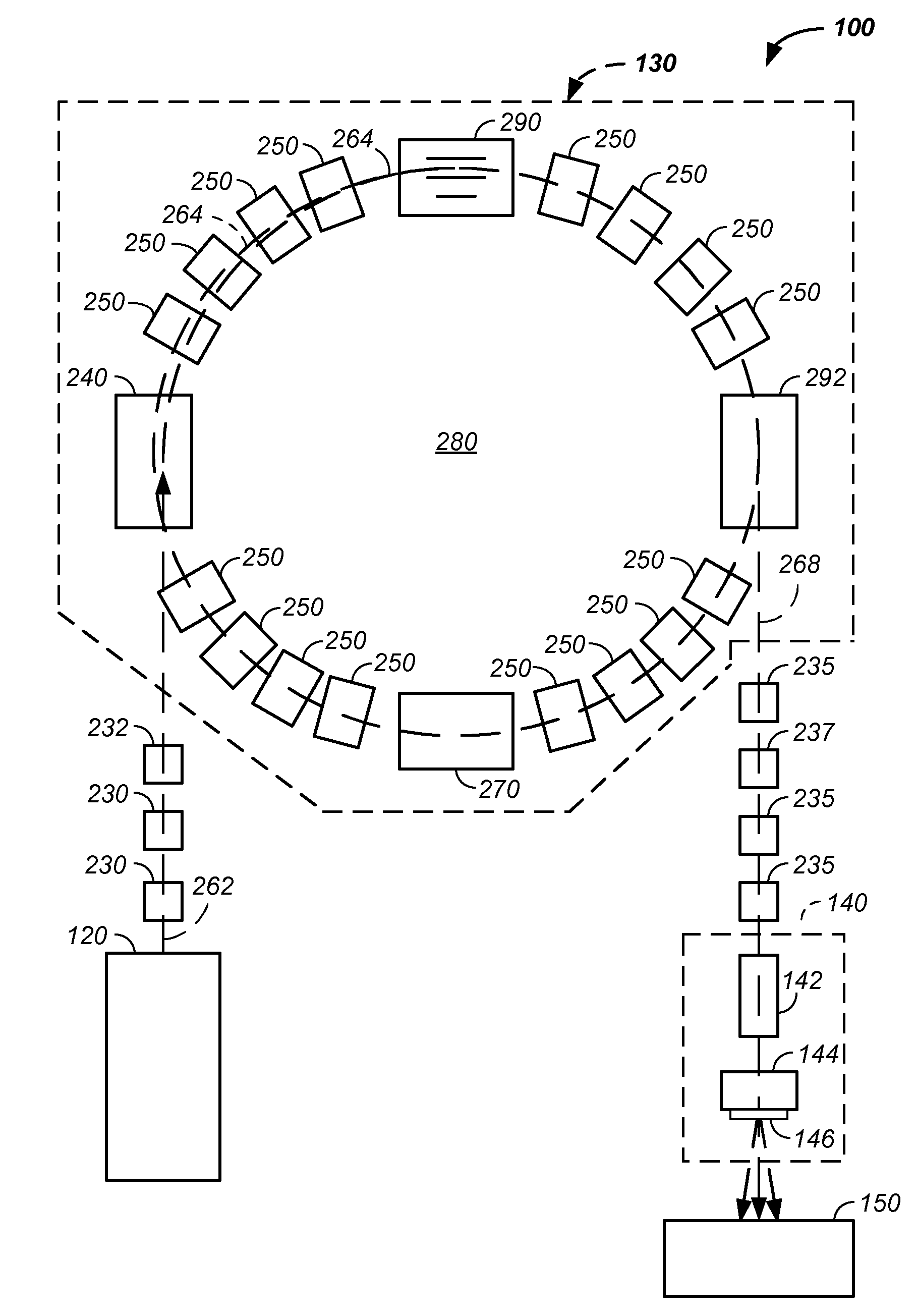
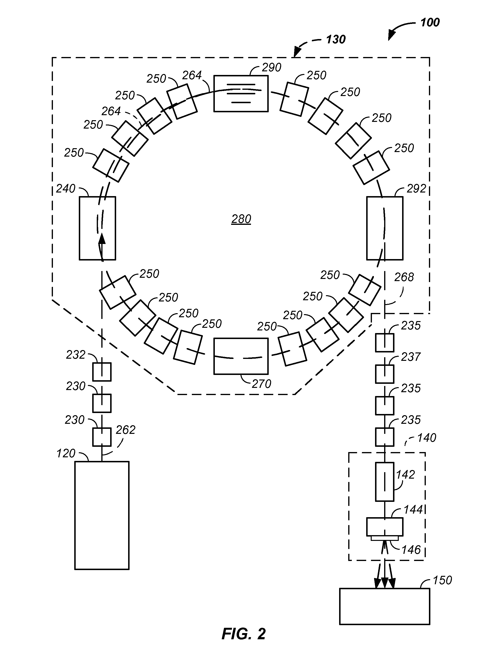
[0085]The invention relates generally to treatment of solid cancers. More particularly, the invention comprises a method and apparatus correlating charged particle beam intensity with charged particle delivery efficiency, optionally in a raster beam scanning mode.

[0086]In one embodiment, a proton beam in a synchrotron traverses through a radio frequency (RF) cavity system. To initiate extraction, an RF field is applied across a first pair of blades in the RF cavity system. The applied RF field applies energy to the circulating charged-particle beam inducing a betatron oscillation. Through timing of the applied RF field, successive passes of the protons through the RF cavity system are forced further and further from the original central beamline. With a sufficient sine wave betatron amplitude, the altered circulating beam path touches an extraction material, such as a foil or a sheet of foil. When the protons traverse through the foil, energy of the protons is lost and the speed of ...


PUM


Abstract

The invention relates to treatment of solid cancers and more particularly to a method and apparatus correlating proton beam intensity with proton delivery efficiency, optionally in a raster beam scanning system. The system induces betatron oscillation on the proton beam causing the beam to traverse an extraction material resulting in slowed protons and a feedback current proportional to the proton flux. A controller receives the desired intensity from an irradiation plan and the feedback current and adjusts the radio-frequency field in the radio-frequency cavity system to yield an intensity of the proton beam that matches the desired intensity from the irradiation plan. Preferably, the intensity of the proton beam correlates with radiation delivery efficiency. The system preferably operates in conjunction with a multi-field charged particle cancer therapy system, with charged particle beam injection, particle beam acceleration, multi-axis charged particle beam control, and / or targeting methods and apparatus.

Description

CROSS-REFERENCES TO RELATED APPLICATIONS[0001]This application:[0002]is a continuation-in-part of U.S. patent application Ser. No. 12 / 425,683 filed Apr. 17, 2009, which claims the benefit of:[0003]U.S. provisional patent application No. 61 / 055,395 filed May 22, 2008;[0004]U.S. provisional patent application No. 61 / 137,574 filed Aug. 1, 2008;[0005]U.S. provisional patent application No. 61 / 192,245 filed Sep. 17, 2008;[0006]U.S. provisional patent application No. 61 / 055,409 filed May 22, 2008;[0007]U.S. provisional patent application No. 61 / 203,308 filed Dec. 22, 2008;[0008]U.S. provisional patent application No. 61 / 188,407 filed Aug. 11, 2008;[0009]U.S. provisional patent application No. 61 / 188,406 filed Aug. 11, 2008;[0010]U.S. provisional patent application No. 61 / 189,815 filed Aug. 25, 2008;[0011]U.S. provisional patent application No. 61 / 201,731 filed Dec. 15, 2008;[0012]U.S. provisional patent application No. 61 / 205,362 filed Jan. 12, 2009;[0013]U.S. provisional patent applicati...

Claims


Application Information

Patent Timeline
Patent Type & Authority Patents(United States)
IPC IPC(8): A61N5/00
CPCA61N5/10A61N5/1043H05H7/10H05H13/04A61N2005/1087
Inventor BALAKIN, VLADIMIR
Owner BALAKIN ANDREY VLADIMIROVICH
Why Eureka
Try Eureka