RF transmitter arrangement for an MR system, and method for determining a setting parameter therefor

a technology of rf transmitter and mr system, which is applied in the direction of magnetic measurement, instruments, measurement devices, etc., can solve the problems of falsifying the measurement, affecting the operation of the system, and the output of the amplifiers, so as to prevent the leakage of rf power from the amplifier output, the effect of substantially preventing the leakage of rf power and reducing the usable output capacity

Active Publication Date: 2005-06-30
SIEMENS HEALTHCARE GMBH
View PDF17 Cites 51 Cited by
  • Summary
  • Abstract
  • Description
  • Claims
  • Application Information

AI Technical Summary

Benefits of technology

[0025] By the inventive use of orthogonal modes with different field distributions, when separate power amplifiers are used for the modes, leakage of RF power from the amplifier outputs can be substantially prevented and, given large signal amplitudes near the modulation limits of the amplifiers, unexpected distortion or over-voltages at the power components can be prevented as well.
[0026] A further advantage of the invention is that the cause of inhomogeneities in the magnetic resonance image is addressed by virtue of the B1 field being effectively optimally homogenously radiated dependent on the examination subject.
[0027] The decoupling of orthogonal modes under load in accordance with the invention is a significant advantage of the radio frequency transmitter arrangement according to the arrangement. In contrast to European Application 1 279 968, the invention uses orthogonal modes in the generation of the B1 field.
[0028] In European Application 1 279 968, the inputs of the resonator segments are decoupled from one another with matching selected reactances (capacitors). With this method, only the reactive component of the coupling impedance (Zjk=Uk/Ij) can be compensated, which is also sufficient with a nearly unloaded resonator. However, if a patient (approximating a conductive cylinder) is introduced, there is the additional coupling via eddy current loops in the patient that are respectively seen by a number of transmitting and receiving channels. Due to the two-fold application of the induction set (Iantenna j→(90°)→Yeddy→(˜0°)→Ieddy→(90...

Problems solved by technology

Temporal and spatial oscillations in the field strengths of the excited B1 field lead to unintended changes in the received MR signal that can falsify the measurement result.
If, in addition to the activation of the rods of a birdcage resonator, separate power amplifiers are used, their outputs leak RF power (some of which...

Method used


Image

  • RF transmitter arrangement for an MR system, and method for determining a setting parameter therefor
  • RF transmitter arrangement for an MR system, and method for determining a setting parameter therefor
  • RF transmitter arrangement for an MR system, and method for determining a setting parameter therefor

Examples


Embodiment Construction

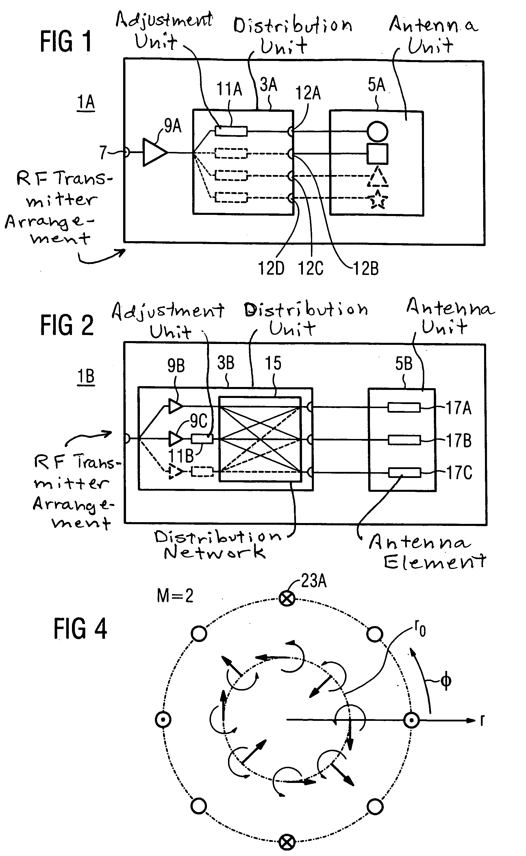
[0055]FIG. 1 schematically shows the design of a radio frequency transmitter unit 1A with a distribution unit 3A and an antenna unit 5A. The RF transmitter unit 1A has an input 7 that can be connected with a radio frequency source. The coupled signal is amplified with a radio frequency amplifier 9A before it is conducted to the distribution unit 3A.

[0056] The distribution unit 3A divides the transmission signal. One of the divided transmission signals (for example the basic transmission signal) proceeds through an adjustment unit 11A for amplitude and / or phase adjustment. The further (auxiliary) transmission signals preferably also are modified with regard to their phase and / or amplitude with adjustment units (indicated dashed). The distribution unit 3A provides at least two mode feed signals that are present at the outputs 12A, 12B, . . . The mode feed signals are conducted to the antenna unit 5A and generate radio frequency fields in a transmission (emission) volume of the antenn...


PUM


Abstract

A radio frequency transmitter arrangement for a magnetic resonance apparatus has a distribution unit and an antenna unit, wherein the antenna unit, to generate radio frequency fields, is fashioned in at least two orthogonal modes, and the distribution unit is fashioned for the division of an RF transmission signal into at least two mode feed signals. At least one adjustment unit is provided to adjust the amplitude and/or phase of one of the mode feed signals and is connected with the antenna unit such that each of the mode feed signals generates a radio frequency field in one of the modes. A multiple transmitter arrangement has at least two radio frequency transmitter arrangements and at least two 180° hybrids. A method is provided to determine at least one setting parameter of the adjustment unit.

Description

RELATED APPLICATION [0001] This application claims the benefit of U.S. Provisional Application No. 60 / 523,100 filed Nov. 19, 2003.BACKGROUND OF THE INVENTION [0002] 1. Field of the Invention [0003] The present invention concerns a radio frequency transmitter arrangement and multiple transmitter arrangement for a magnetic resonance system as well as method to determine a setting parameter of such a transmitter arrangement. [0004] 2. Description of the Prior Art [0005] Magnetic resonance (MR) tomography is a technique to acquire images of the inside of the body of a living examination subject. An examination subject is exposed to an optimally homogenous static basic magnetic field (designated as a B0 field) that is generated by a basic field magnet of an MR apparatus. During the acquisition of the MR images, rapidly switched gradient fields, generated by gradient coils, are superimposed on this basic magnetic field for spatial coding. [0006] RF energy pulses of a defined field strengt...

Claims


Application Information

Patent Timeline
IPC IPC(8): G01R33/34G01R33/36
CPCG01R33/246G01R33/34046G01R33/34061G01R33/5659G01R33/3607G01R33/5612G01R33/3415
Inventor FEIWEIER, THORSTENOPPELT, RALPHRENZ, WOLFGANGVESTER, MARKUS
Owner SIEMENS HEALTHCARE GMBH
Why Eureka
Try Eureka