Much of the
patent literature surrounding these radio tags and RFID tags as well as the published literature uses terminology that has not been well defined and can be confusing.
Many of the patents which are referenced below do not make many distinctions outlined in the above glossary and their authors may not at that time been fully informed about the functional significance of the differences outlined above.
This multifrequency approach limited data to about five bits to eight bits and the range of the devices was limited to only a few inches.
These two patents also teach that steel and other conductive metals may detune the antennas and degrade performance.
The
ceramic filter required to increase the frequency from 50 kHz to a
high frequency is, however, an expensive large external component, and phase-locked loops or other methods commonly used to multiply a frequency upward would consume considerable power.
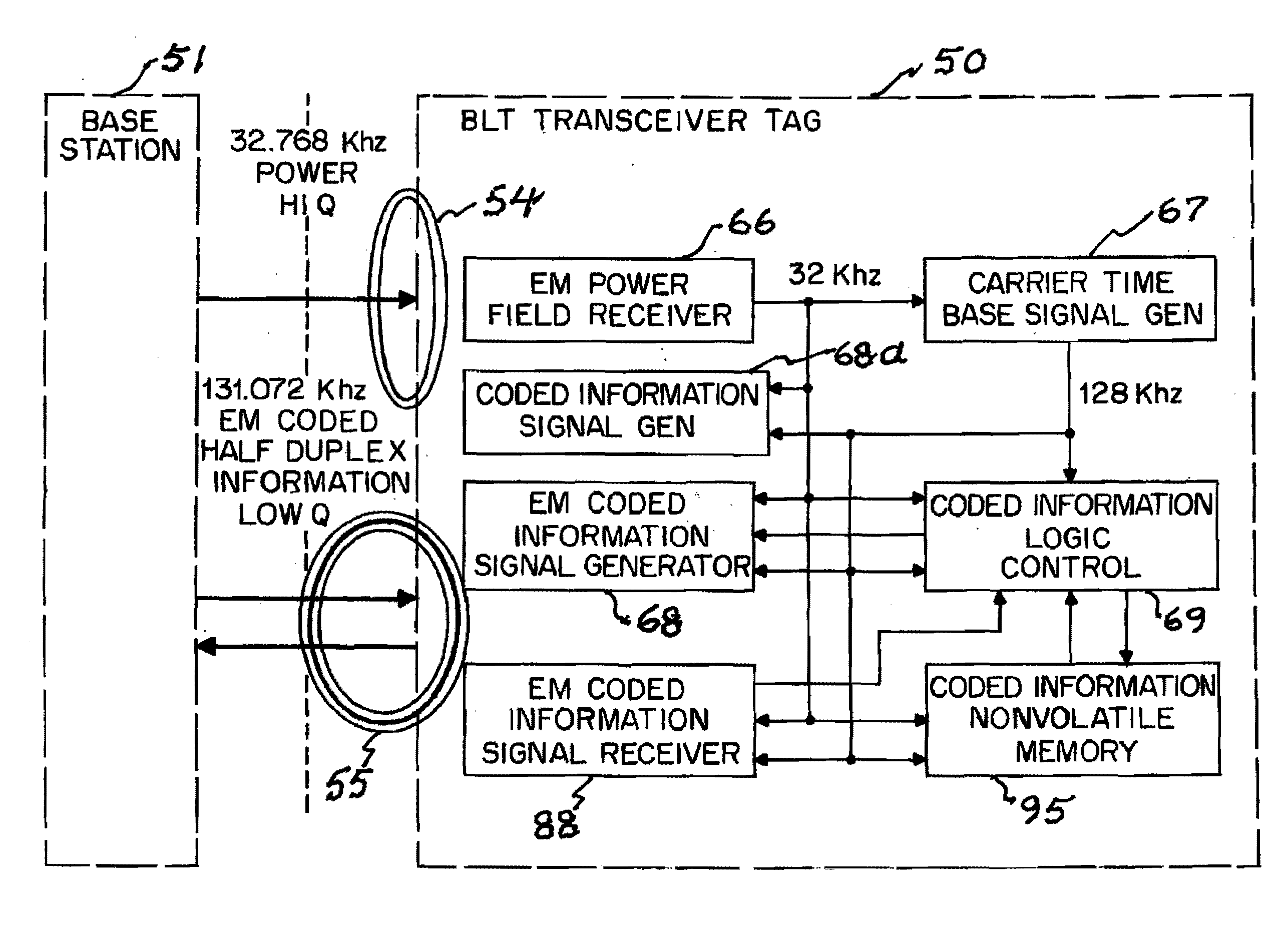
This non-radiating mode reduces the power required to operate a tag and puts the detection burden on the
base station.
HF and UHF tags are unable to use the carrier as a time base because the speed would require high speed chips and
power consumption would be too high.
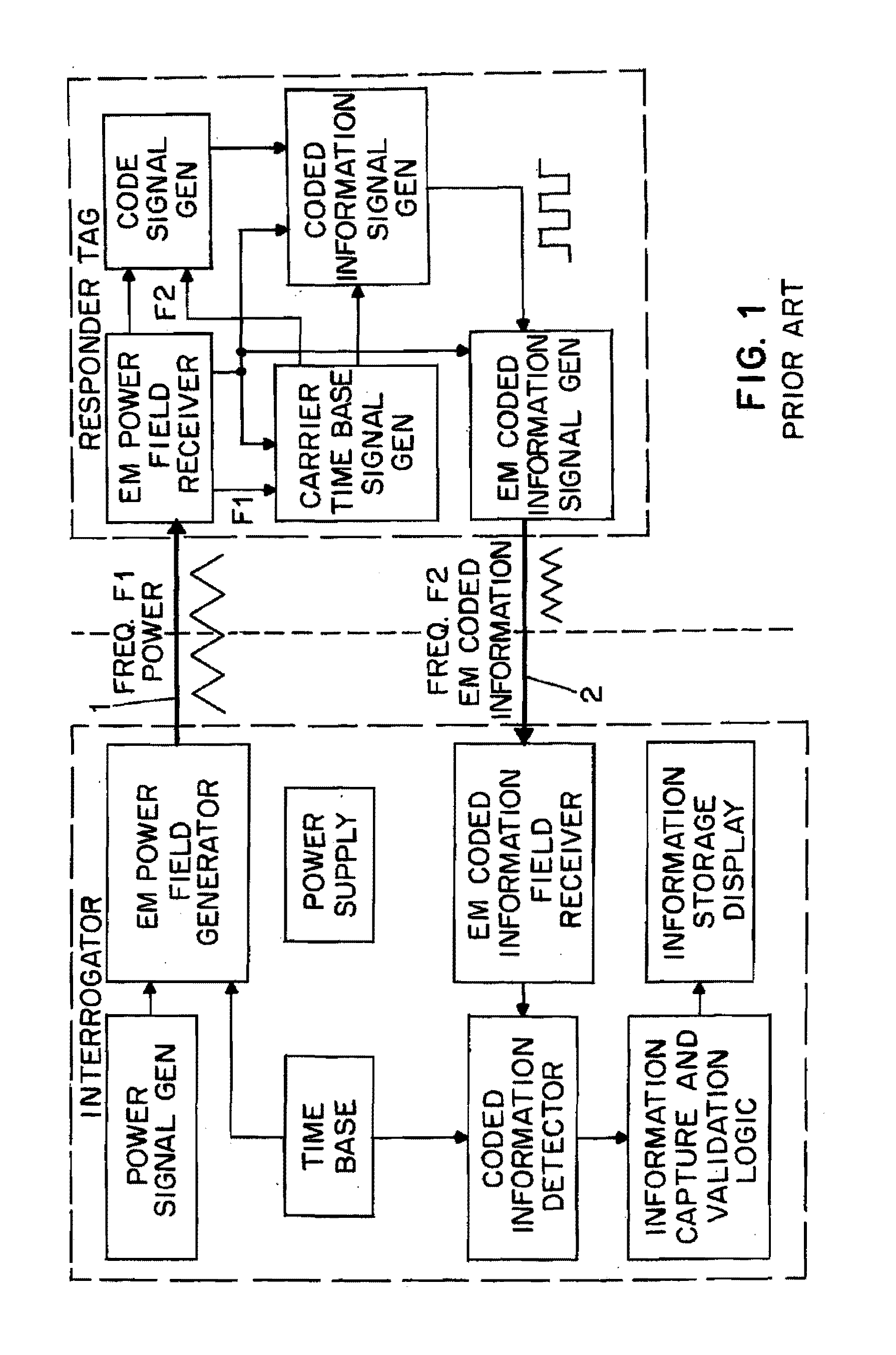
The major
disadvantage of the prior art backscattered mode radio tag, is that it has limited power, limited range, and is susceptible to
noise and reflections over a radiating active device.
As a result many backscattered tags do not work reliably in harsh environments and require a directional “
line of sight” antenna.
However, since all of these tags use high frequencies the tags must continue to operate in backscattered mode to conserve battery life.
The power consumed by any
electronic circuit tends to increase with the frequency of operation.
Because these tags are active backscattered transponders they cannot work in an on-demand peer-to-peer network setting, and they require line-of-
sight antennas that provide a carrier that “illuminates” an area or zone or an array of carrier beacons.
These tags do provide full functionality and what might be called Real-Time
Visibility, but they are expensive (over $100.00 US) and large (videotape size, 6¼ inch by 2⅛ inch by 1⅛ inch) because of the power issues described above and must use replaceable batteries since even with such a 1.5 inch by 6 inch Li battery these tags are only capable of 2,500 reads and writes.
Finally active radiating transceiver tags require large batteries, are expensive and may cost tens to hundreds of dollars.
One of the major disadvantages of a passive nonradiating
system is that it requires the use of handheld readers or portals to read tags and changes
in process control (e.g., U.S. Pat. No. 6,738,628: Electronic Physical
Asset Tracking, 2004).
It will also be appreciated that the prior art has assumed
low frequency tags to be slow, short range, and too costly.
Many of the commercial organizations recommending these higher frequencies believe that passive and active radio tags in these low frequencies are not suitable for any of these applications for reasons given above.
The transmission speed is inherently slow using ULF as compared to HF and UHF since the tag must communicate with low
baud rates because of the
low transmission carrier frequency.
Many sources of
noise exist at these ULF frequencies from electronic devices, motors, fluorescent ballasts, computer systems, power cables.
Thus ULF is often thought to be inherently more susceptible to
noise.
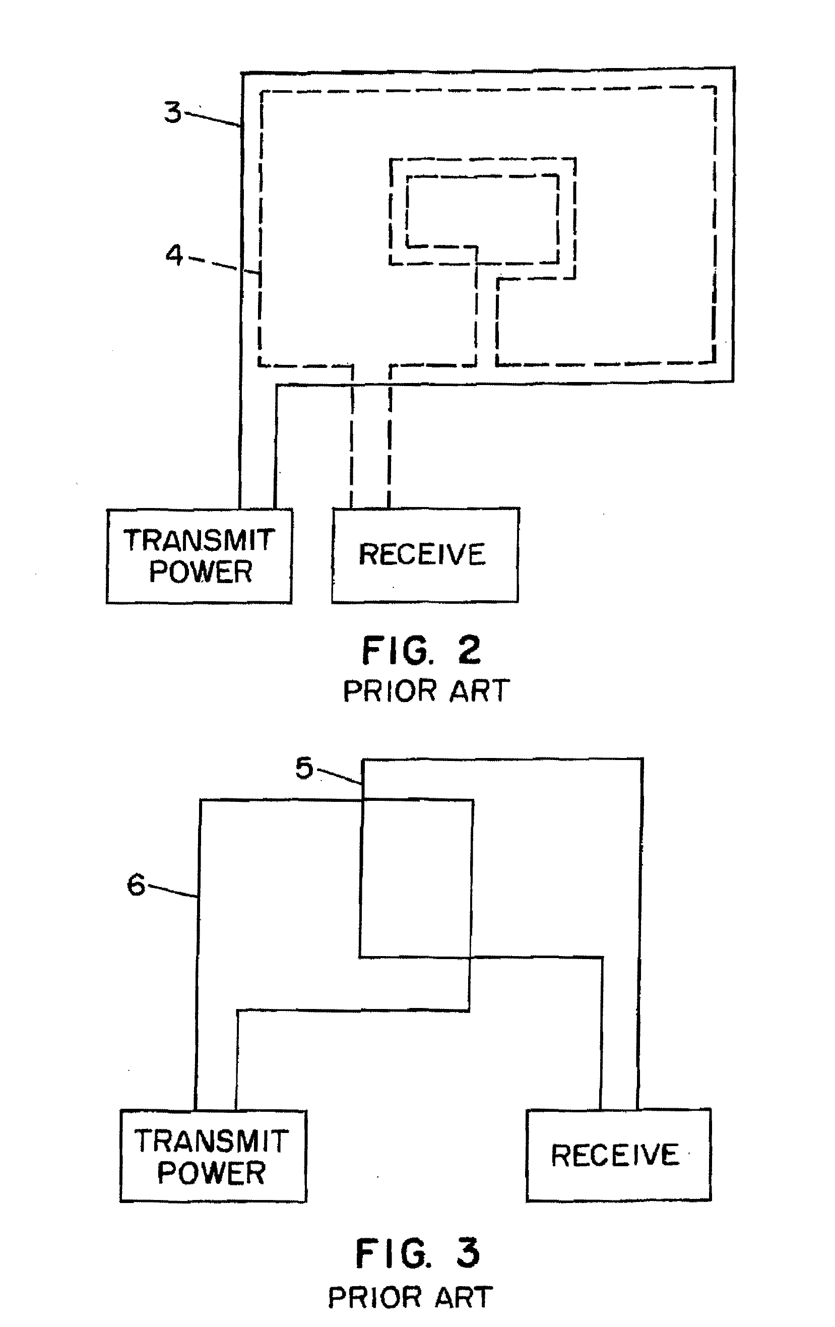
Radio tags in this frequency range are thought to be more expensive since they require a wound coil antenna because of the requirement for many turns to achieve optimal electrical properties (maximum Q).
In contrast HF and UHF tags can use antennas etched directly on a
printed circuit board and ULF would have even more serious distance limitations with such an antenna.
Current networking methods used by
high frequency tags, as used in HF and UHF, are impractical due to such low bandwidth of ULF tags described immediately above.

