RF power supply for a mass spectrometer

a mass spectrometer and power supply technology, applied in the field of mass spectrometer radio frequency (rf) power supply, can solve the problem of rapid collapse of the signal in the secondary winding, and achieve the effect of fast recovery of the rf signal

Active Publication Date: 2009-03-03
THERMO FINNIGAN
View PDF5 Cites 55 Cited by
  • Summary
  • Abstract
  • Description
  • Claims
  • Application Information

AI Technical Summary

Benefits of technology

[0023]Optionally, the power supply further comprises a buffer capacitance connected to the switch, thereby allowing faster recovery of RF signals in the secondary winding upon disconnection of the shunt.
[0028]Furthermore, variable and different DC offsets may be used for different filars, to create a potential well or potential gradient between electrodes. This potential well may be advantageous in trapping ions within a storage device or for their ejection.
[0043]Generally, ions will orbit around the longitudinal axis following complex paths. These ions are thus ejected in a direction substantially orthogonal to the longitudinal axis, i.e. in a direction more or less at right angles to the points on the longitudinal axis the ion is currently passing. This direction is towards the concave side of the ion trap to ensure the many possible ion paths converge. The curvature of the ion trap and the position of the mass analyser are such that the ion paths converge at the entrance to the mass analyser, thereby focussing the ions.

Problems solved by technology

The rapid diversion of current through the shunt leads to a rapid collapse of the signal in the secondary winding and, hence, to the RF field generated by the electrodes.

Method used


Image

  • RF power supply for a mass spectrometer
  • RF power supply for a mass spectrometer
  • RF power supply for a mass spectrometer

Examples


fourth embodiment

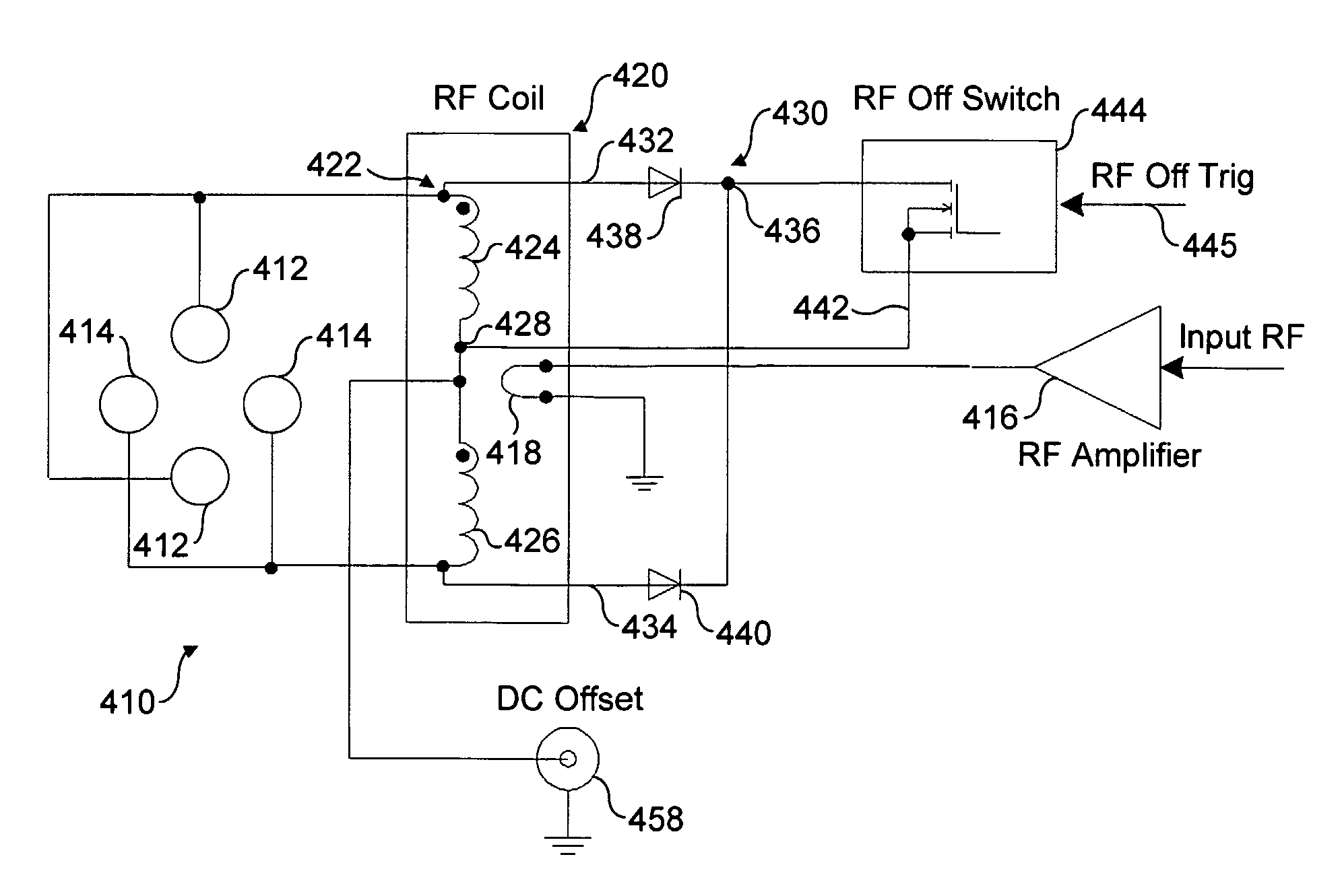
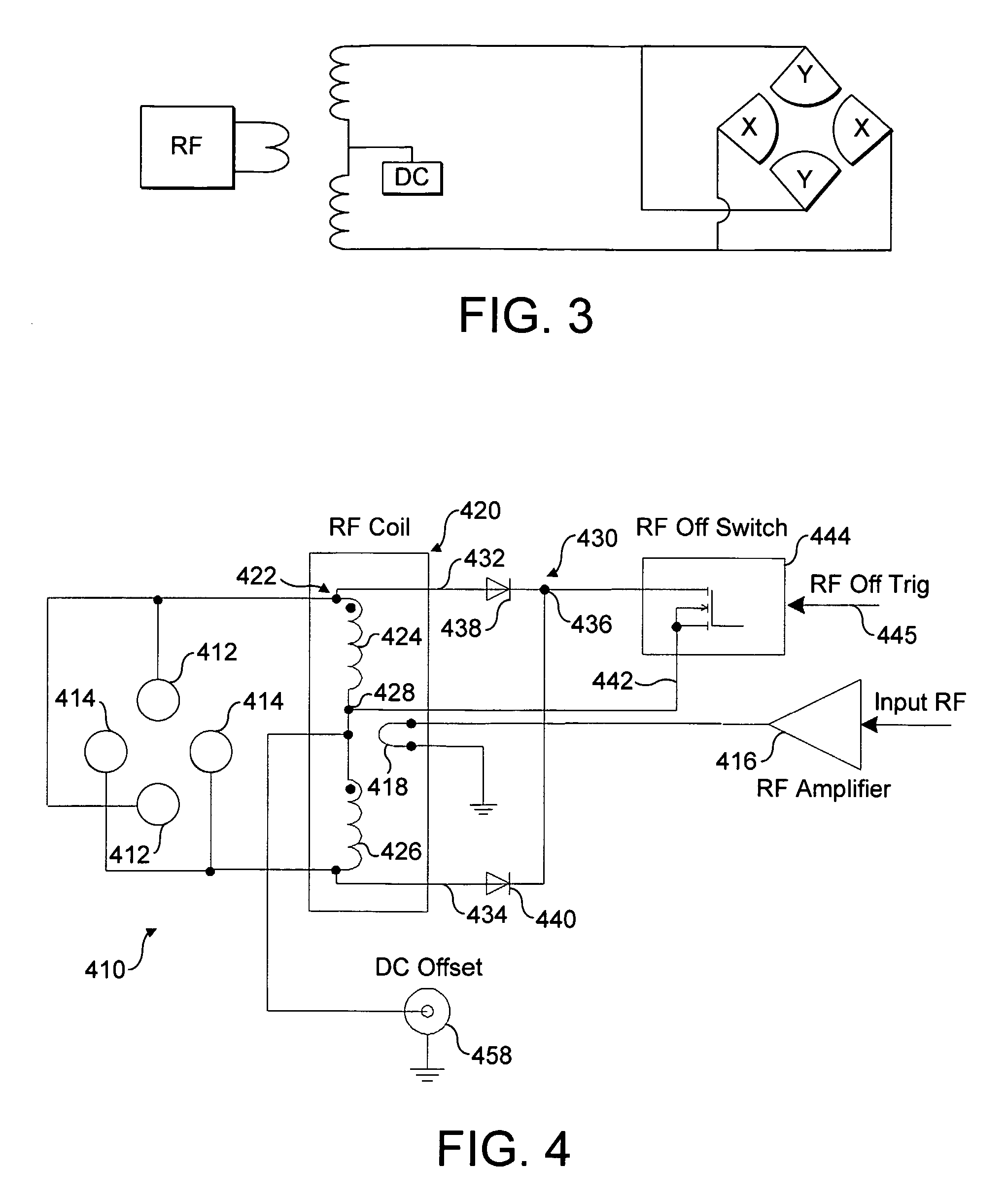
[0069]FIG. 9 shows a power supply 910 according to the present invention that ensures more rapid re-establishment of the RF field in the ion trap when switch 944 is opened to remove the shunt. FIG. 9 shares many of the features of FIG. 4. Thus, as mentioned above, like reference numerals are used, merely replacing the leading “4” by a leading “9” so that, for example, switch 444 becomes switch 944.

[0070]As can be seen from FIG. 6, the voltage waveform 612 that arises on opening the switch 944 has an attenuated amplitude that increases to reach the amplitude of the previous voltage waveform 610. This recovery time does in fact depend upon several parameters, for example the power of the RF amplifier 916 and the internal capacitance of the switch 944, among other things. This problem can be addressed by the inclusion of a further electrical path 960 that runs from the shunt 942 that connects switch944 to central tap 928, the electrical path 960 also extending to the switch 944 that no...

fifth embodiment

[0071]FIG. 10 shows a power supply 1010 according to the present invention. As for FIGS. 4, 8 and 9, many features are shared and so will not be described again. The same numbering convention is also adopted where the leading “4” has now been replaced by a leading “10”.

[0072]The transformer 1020 of FIG. 10 comprises a multi-filar secondary 1022 having a first pair of symmetrical, connected windings 1024 and 1026, and a second pair of symmetrical, connected windings 1070 and 1072, wherein the first and second pair are not connected to each other. Both the first and second pair of secondary windings are arranged adjacent one another in juxtaposition such that the RF signal passing through the primary 1018 induces a RF signal in both pairs of secondary windings. The first pair of secondary windings 1024 and 1026 are connected to the full-wave rectifier 1030 in exactly the same fashion as shown in FIG. 9. That is to say, the full-wave rectifier 1030 includes a buffer capacitance 1062 an...

sixth embodiment

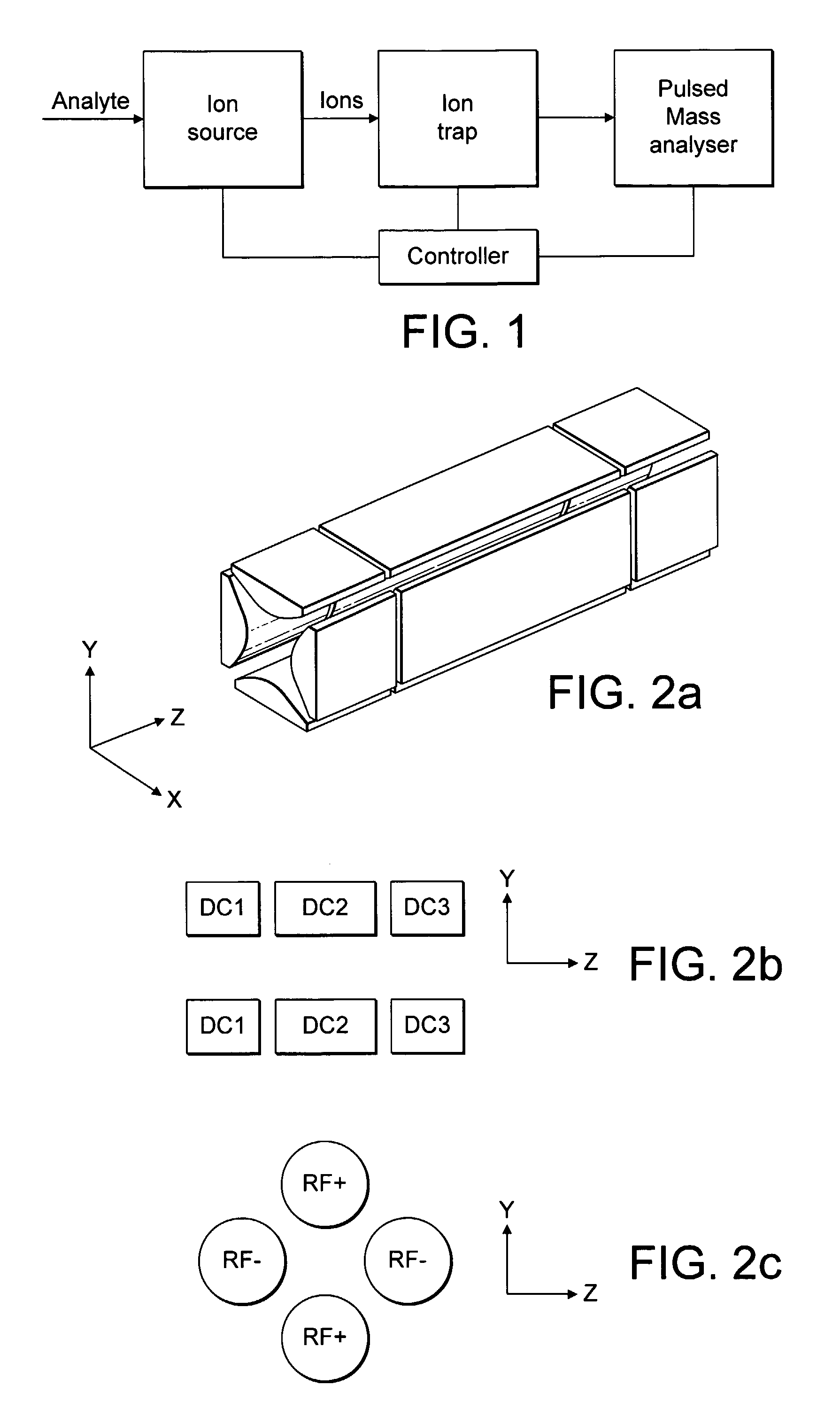
[0075]FIG. 11a shows a power supply according to the present invention. This embodiment shows in more detail an arrangement for providing orthogonal extraction of ions stored in the ion trap in the x-axis direction, also shown in FIG. 11a. To facilitate extraction, a slot is provided in electrode 1114′ as indicated at 1188. A similar extraction arrangement of a slot 1188 within an electrode 1114′ can be used in any of the other embodiments. Similar to FIG. 9, the embodiment of FIG. 11a uses a multi-filar secondary 1122, this time comprising three pairs of symmetrical secondary windings. A first pair of symmetrical windings 1124 and 1126 are connected to the full-wave rectifier 1130. As before, either the basic switch circuit of FIG. 4 may be used or, as is shown in FIG. 11a, a more complicated switch 1144 including buffer capacitance 1162 may be employed instead.

[0076]In the embodiment of FIG. 11a, each of the four electrodes are treated separately. Accordingly, they are now labelle...


PUM


Abstract

The present invention provides a radio frequency (RF) power supply in a mass spectrometer. The power supply provides an RF signal to electrodes of a storage device to create a trapping field. Such ion storage devices are often used to store ions prior to ejection to a subsequent mass analyzer. The RF field is usually collapsed prior to ion ejection. The present invention provides a RF power supply comprising: a RF signal supply, a coil arranged to receive the signal provided by the RF signal supply and to provide an output RF signal for supply to electrodes of an ion storage device, and a shunt including a switch operative to switch between a first open position and a second closed position in which the shunt including a switch operative to switch between a first open position and a second closed position in which the shunt shorts the coil output.

Description

BACKGROUND OF THE INVENTION[0001]This invention relates to a mass spectrometer radio frequency (RF) power supply for applying a RF field to an ion storage device and to a method of operating an ion storage device using a RF field. In particular, but not exclusively, this invention relates to an ion storage device that contains or traps ions using a RF field prior to ejection to a pulsed mass analyser.[0002]Such traps could be used in order to provide a buffer for the incoming stream of ions and to prepare a packet with spatial, angular and temporal characteristics adequate for the specific mass analyser. Examples of pulsed mass analysers include time-of-flight (TOF), Fourier transform ion cyclotron resonance (FT ICR), Orbitrap types (i.e. those using electrostatic only trapping), or a further ion trap. A block diagram of a typical mass spectrometer with an ion trap is shown in FIG. 1. The mass spectrometer comprises an ion source that generates and supplies ions to be analysed to an...

Claims


Application Information

Patent Timeline
Patent Type & Authority Patents(United States)
IPC IPC(8): H01J49/42B01D59/44H01J49/02
CPCH01J49/022H01J49/423H01J49/427H01J49/0031H01J49/36
Inventor MAKAROV, ALEXANDER ALEKSEEVICHDENISOV, EDUARD V.KHOLOMEEV, ALEXANDER
Owner THERMO FINNIGAN
Why Eureka
Try Eureka