Laying of conduit at sea using horizontal reels

a technology of horizontal reels and conduits, which is applied in the direction of pipe laying and repair, pipe laying vessels, mechanical equipment, etc., can solve the problems of time-consuming and inefficient process of spooling, complex process, and specialized lay vessels, and achieves the effect of speeding up the process, saving time and cos

Active Publication Date: 2016-02-02
SAIPEM SPA
View PDF16 Cites 4 Cited by
  • Summary
  • Abstract
  • Description
  • Claims
  • Application Information

AI Technical Summary

Benefits of technology

[0006]The present invention provides, according to a first aspect, a method of laying conduit at sea from a reel vessel, wherein the method includes the steps of (a) laying conduit from a first reel of conduit, the first reel rotating about a first substantially vertical axis, and (b) laying conduit from a second reel of conduit, the second reel rotating about a second substantially vertical axis spaced apart from the first substantially vertical axis, wherein a portion of the route travelled on the vessel by the conduit during the step of laying conduit from the first reel of conduit is substantially the same as a portion of the route travelled by the conduit during the step of laying conduit from the second reel of conduit. Such an arrangement may be facilitated by the conduit from the second reel passing around at least part of the periphery of the first reel, and preferably then following substantially the same route from the first reel to the point at which the conduit leaves the vessel. Thus, efficient space may be used on the vessel, for example on deck, because once a suitable route has been provided for conduit to travel from the second reel to a point at which the conduit can utilize the route used during laying of conduit from the first reel, no further special equipment need be provided. Utilizing such equipment / route, or part thereof, both for laying conduit from the first reel and for laying conduit from the second reel also facilitates an efficient, cost-effective, and speedy means for laying conduit on a lay-project where the length of conduit to be laid needs to be accommodated on more than one reel. The conduit from the second reel may pass along a curved path that at least partially circumnavigates around the first reel (for example, broadly following its circumference, whether spaced apart therefrom or not).
[0010]Given that the conduit is laid from a reel vessel, which is suitable therefore for laying very long pipeline (typically, resulting in a very heavy reel, when fully stocked), the type of conduit laid will typically be conduit that has a function in the offshore oil and gas industry and one which is sufficiently long and / or of a suitably wide diameter to make it economically sensible for a reel vessel to be used to lay it. It will be appreciated that the conduit, whilst being laid at sea, may not be laid entirely on the ocean floor. Indeed when laying, it may be the intention for a large proportion, perhaps all, of the conduit to be held off of the ocean floor. The conduit may be in the form of pipeline. The pipeline may be configured for use as a riser. The pipeline may be rigid pipeline. The pipeline may be in the form of flexible pipeline. Rigid pipeline, as well as flexible pipeline, has at least some flexibility but reeled rigid pipeline will typically need to be plastically deformed to ensure that the pipeline once laid remains relatively straight and / or free of residual stresses. The pipeline may be made of metal. The metal pipeline may be coated with another material. The pipeline may be formed of sections welded together end-to-end to form the pipeline. The pipeline may be in the form of pipe-in-pipe pipeline. The pipeline may for example be a double-walled pipeline, the wall being defined by an inner pipe and an outer pipe. There may be more than two layers to the wall of the pipeline. The conduit may be in the form of umbilical, for example for use in the offshore gas and oil industry. Umbilical may facilitate the flow of hydraulic fluid. Umbilical may facilitate the supply of control or communications signals. Umbilical may facilitate the supply of electric power. Umbilical may facilitate the flow via one or more relatively large diameter pipes of gas / oil for bulk flows.
[0024]The positions of the reel stations are preferably so arranged that the first vertical axis is displaced from the position of the second vertical axis both in a direction along the length of the vessel and in a direction across the width of the vessel. Such a staggered arrangement may facilitate more efficient use of space on the vessel. The present invention recognizes that there is no need, at least insofar as making efficient use of space on the vessel, for the reels to be arranged symmetrically on the vessel. Indeed, more efficient use of the space may be achieved by mean of non-symmetrical arrangements of the reels.

Problems solved by technology

Unspooling pipe from a reel at sea requires a complex, specialized lay vessel, particularly when laying relatively long or larger diameter pipelines.
A drawback of the current reel pipelaying systems is that spooling is a time-consuming and inefficient process.

Method used


Image

  • Laying of conduit at sea using horizontal reels
  • Laying of conduit at sea using horizontal reels
  • Laying of conduit at sea using horizontal reels

Examples


Embodiment Construction

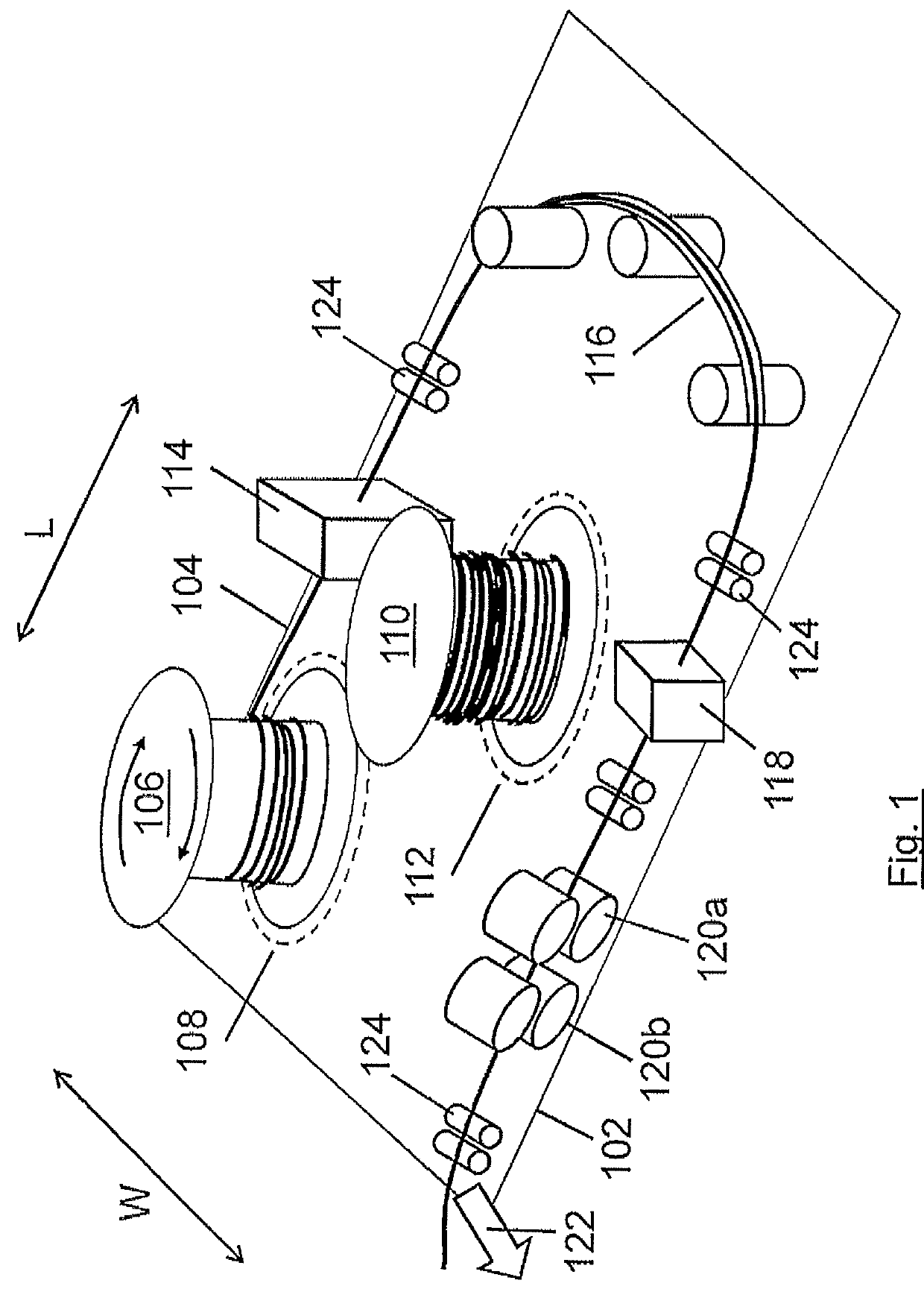
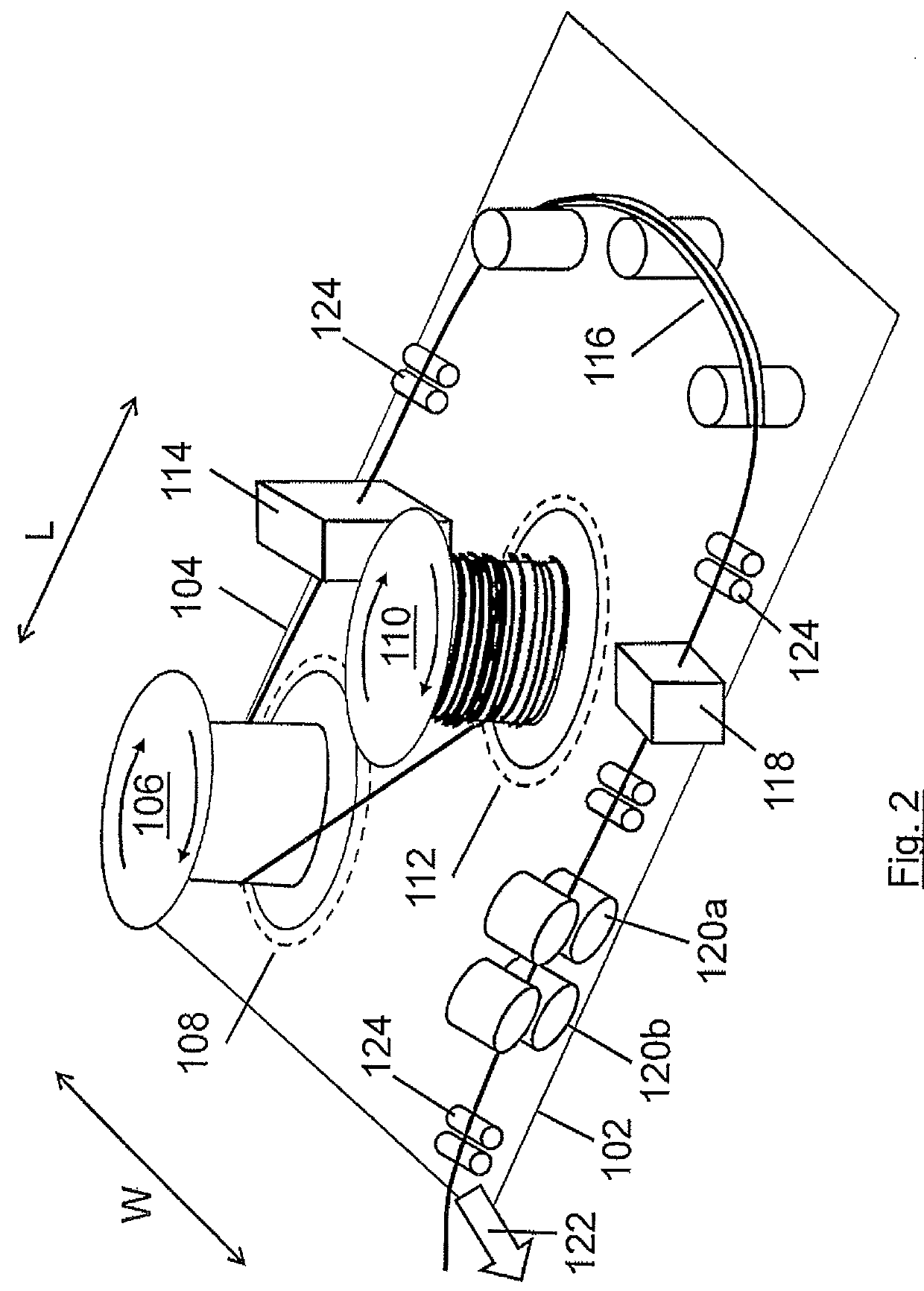
[0031]FIG. 1 shows a vessel (part only of the deck 102 being shown in FIG. 1) for laying rigid pipe 104 according to a first embodiment of the invention. The vessel includes a first horizontal pipe reel 106 at a first reel station 108 and a second horizontal pipe reel 110 at a second reel station 112. Both reels are permanently mounted on the deck 102 of the vessel for rotation about respective vertical axes spaced apart both with respect to the length L of the vessel and the width W of the vessel.

[0032]The use of the vessel to lay rigid pipe from the first reel will now be described. Rigid pipe 104 is paid out from the first reel 106 and passes via a spooling tower 114, and via an arcuate chute 116, to a pipe straightening apparatus 118. The pipe then passes via two sets of pipe tensioners 120a, 120b before exiting the vessel via a stinger ramp (not separately shown in FIG. 1 but illustrated schematically by arrow 122). The pipe is additionally supported by rollers 124 as it passes...


PUM


Abstract

A method of laying conduit at sea from a reel vessel includes the steps of laying conduit, for example pipeline or umbilical, from a first reel which rotates about a first substantially vertical axis. Conduit is laid from a second reel of conduit rotating about a second substantially vertical axis spaced apart from the first axis. A portion of the route travelled by the conduit during the step of laying conduit from the first reel of conduit is substantially the same as a portion of the route travelled by the conduit during the step of laying conduit from the second reel of conduit, for example, the conduit from the second reel may pass around a part of the periphery of the first reel and then follow substantially the same path as previously travelled by the conduit laid from the first reel.

Description

BACKGROUND OF THE INVENTION[0001]The present invention concerns a method of laying of conduit at sea using one or more horizontal reels, each reel thus having a substantially vertical axis, and a vessel for performing such a method. The present invention is particularly, but not exclusively, concerned with laying of pipeline with reel vessels.[0002]A reel vessel is a ship or barge specially designed to handle a pipeline that is wound onto a large and massive reel. Reel vessels are therefore relative large and massive and are used predominantly for laying flexible pipeline, rigid pipeline, and risers, and sometimes umbilical. Pipe-laying from a reel vessel has the great benefit of allowing the bulk of the welding, coating and inspecting of the pipeline to be carried out in factory conditions ashore to form a continuous length of pipe, which is then spooled onto a storage reel on the vessel, prior to being unspooled during pipe-lay operations. Unspooling pipe from a reel at sea requir...

Claims


Application Information

Patent Timeline
Patent Type & Authority Patents(United States)
IPC IPC(8): F16L1/12F16L1/20F16L1/23B63B35/03
CPCF16L1/203B63B35/03F16L1/12F16L1/205F16L1/23
Inventor ARDAVANIS, KIMON TULLIOVINCIGUERRA, MICHELEDONELLI, DARIO
Owner SAIPEM SPA
Why Eureka
Try Eureka