Tunable photonic RF circulator for simultaneous transmit and receive

Active Publication Date: 2016-02-02
HRL LAB
View PDF15 Cites 31 Cited by
  • Summary
  • Abstract
  • Description
  • Claims
  • Application Information

AI Technical Summary

Benefits of technology

[0012]In addition, the photonic RF circulator according to the principles of the present invention is coupled to a single antenna or antenna array element. Also, the photonic RF circulator according to the principles of the present invention couples modulated light of the same wavelength that are obtained from two different optical waveguide gratings, into a set of differential photodetectors. Compared to the prior approach, the

Problems solved by technology

Also, the prior approach has the disadvantage that its performance depends on having the sec

Method used


Image

  • Tunable photonic RF circulator for simultaneous transmit and receive
  • Tunable photonic RF circulator for simultaneous transmit and receive
  • Tunable photonic RF circulator for simultaneous transmit and receive

Examples


Embodiment Construction

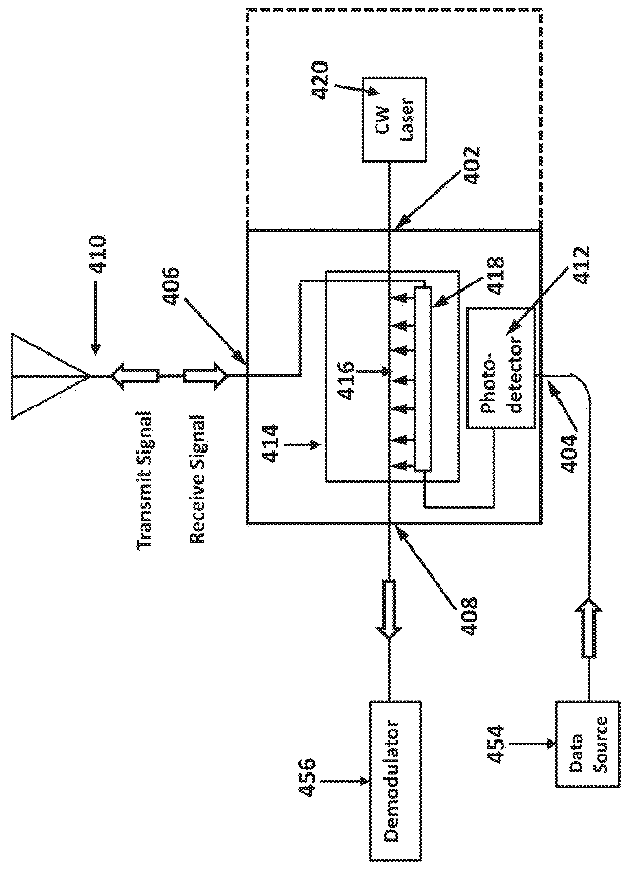
[0031]FIG. 5 shows one embodiment of the photonic RF circulator 500 according to the principles of the present invention. This photonic RF circulator 500 has a transmit input 501 that is coupled to a source of a transmit signal and a receive output 503 that typically is coupled to an RF receiver. The RF transmit signal travels from the signal source through the photonic RF circulator 500 to an antenna 514. An RF received signal, received by the antenna 514, travels from the antenna 514 through the photonic RF circulator 500 to the RF receiver via the receive output 503. The path between the photonic RF circulator 500 and the antenna 514 is bi-directional. In many applications it is desirable for the antenna 514 to simultaneously transmit a signal, at a given frequency, and receive a signal, at that same frequency (or a nearby frequency). Such simultaneous transmit and receive (STAR) operation is made possible by the photonic RF circulator 500. The photonic RF circulator 500 accordin...


PUM


Abstract

An photonic RF circulator is described that provides greater than 40 db of isolation between a Received RF signal and a Transmitted RF signal in a simultaneous transmit and receive device. The photonic RF circulator uses light modulated in an optical waveguide grating where the Received RF signal co-propagates with the light and the Transmitted RF signal counter-propagates with the light. Variations described within provide for broadening the bandwidth of the T/R isolation and rejection of various noise sources.

Description

CROSS REFERENCE TO RELATED APPLICATIONS[0001]This application claims priority to provisional application 61 / 546,804 titled “Tunable Photonic RF Circulator and Antenna” filed Oct. 13, 2011. The contents of which are incorporated by reference herein.TECHNICAL FIELD[0002]This disclosure relates to a Radio Frequency (RF) circulator suitable for isolating the transmitted and received RF signals in a Simultaneous Transmit And Receive system (STAR).BACKGROUND[0003]Components used in optical or photonic links such as a laser, an optoelectronic modulator and a photodetector have been used in optical circulators for RF applications with limited success.[0004]Prior art RF circulators based on ferrite isolators may achieve Transmit and Receive (T / R) isolation of 20-25 dB over a fairly large (e.g., octave) bandwidth. Although these ferrite isolators have T / R isolation notches whose enhanced isolation is as great as 40 dB, it is difficult or at least cumbersome to tune the frequency of these deep...

Claims


Application Information

Patent Timeline
IPC IPC(8): G02B6/42G02B6/02H01P1/38G02F1/01G02B6/12
CPCG02F1/011H01P1/38G02B6/4279G02B6/02076G02B2006/12142H04B2210/006G02F1/0356G02F2201/305
Inventor YAP, DANIELSCHAFFNER, JAMES H.EFIMOV, OLEG M.
Owner HRL LAB
Why Eureka
Try Eureka