
Vacuum brake servo for a motor vehicle braking system

a technology for brake systems and vacuum brakes, which is applied in the direction of brake systems, mechanical equipment, transportation and packaging, etc., can solve the problems of insufficient durability and increase the production cost of such brake boosters, and achieve the effect of simple and inexpensive means and effective reduction of inflow nois

Active Publication Date: 2016-02-16
LUCAS AUTOMOTIVE GMBH
View PDF26 Cites 2 Cited by
  • Summary
  • Abstract
  • Description
  • Claims
  • Application Information

AI Technical Summary

Benefits of technology

This invention provides a way to reduce the noises in a vacuum brake booster by creating a guiding channel with a constant flow diameter that is smaller than the downstream sealing seat, resulting in a calming of the air flow. This reduces the nokes in a frequency range that can be annoying. It can be done by adding a separate component or by using a guiding channel sleeve that is simple and inexpensive. The guiding channel can be of stepped form with flow channel sections of different diameters or can be smoothly rounded to promote smooth air flow and flow calming.

Problems solved by technology

These include, for example, the intake noise of a vacuum brake booster, which occurs when the brake booster is actuated from its rest position.
All the solutions from the prior art provide additional parts with relatively complicated geometry which increase the production costs of such brake boosters undesirably.
Moreover, durability problems may arise when using foam parts.

Method used


Image

  • Vacuum brake servo for a motor vehicle braking system
  • Vacuum brake servo for a motor vehicle braking system
  • Vacuum brake servo for a motor vehicle braking system

Examples


Embodiment Construction

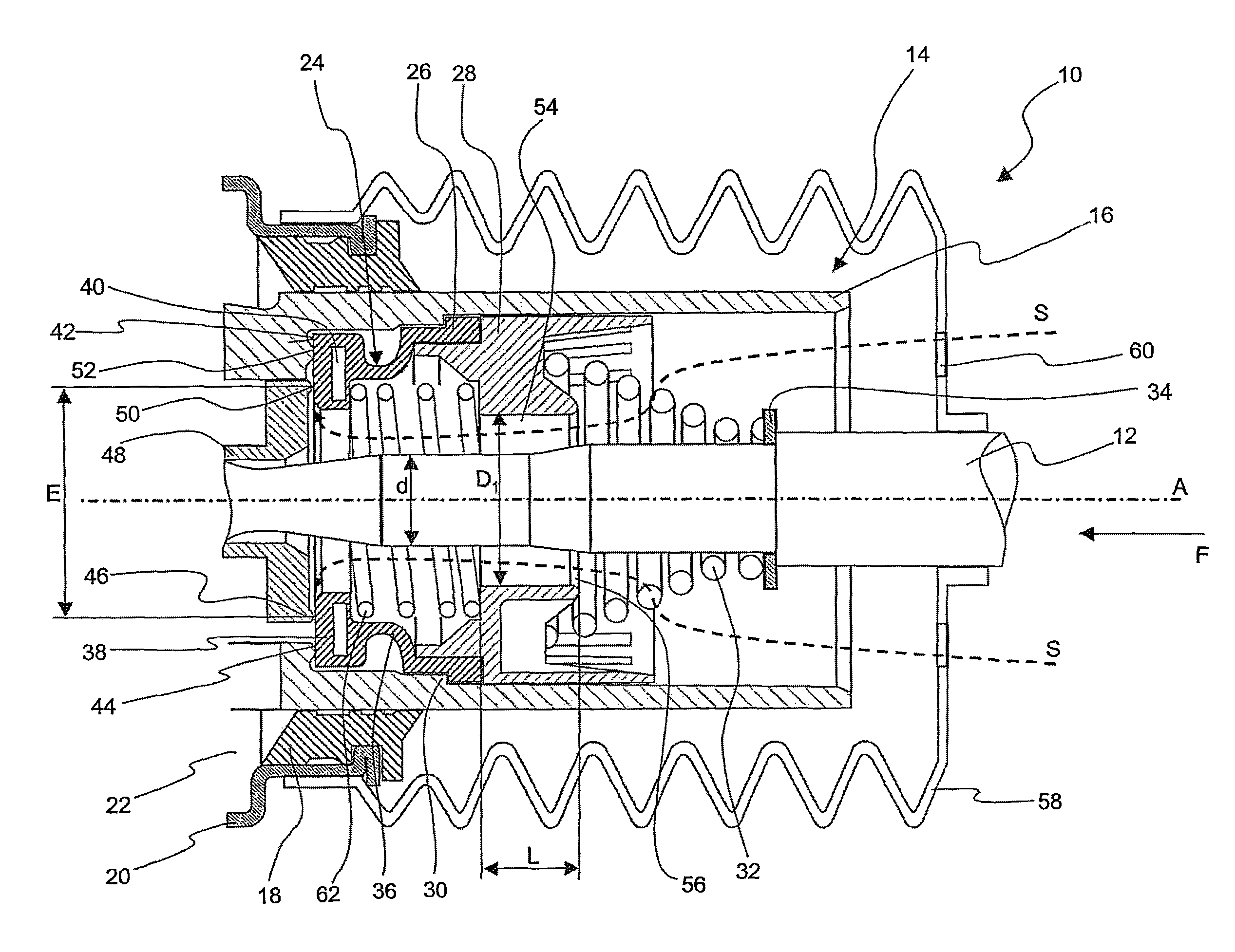
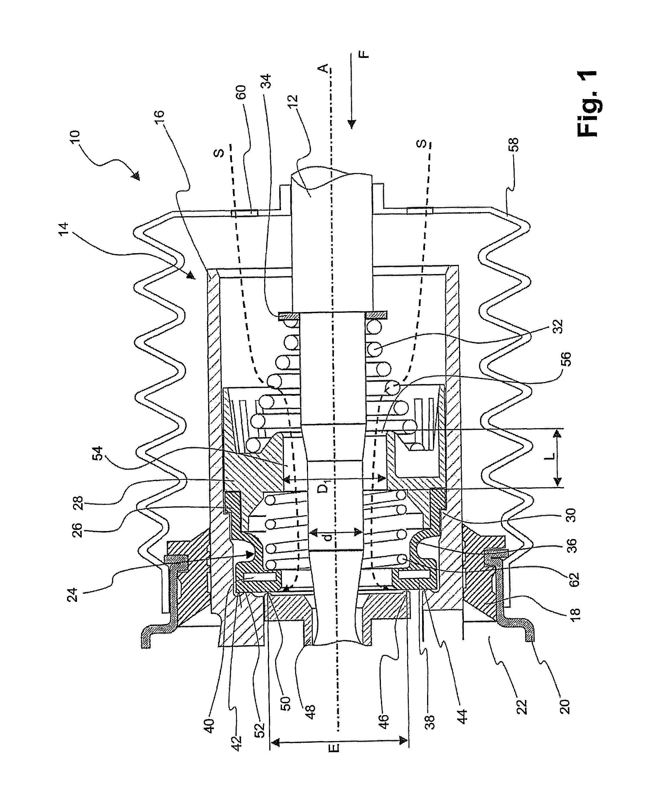
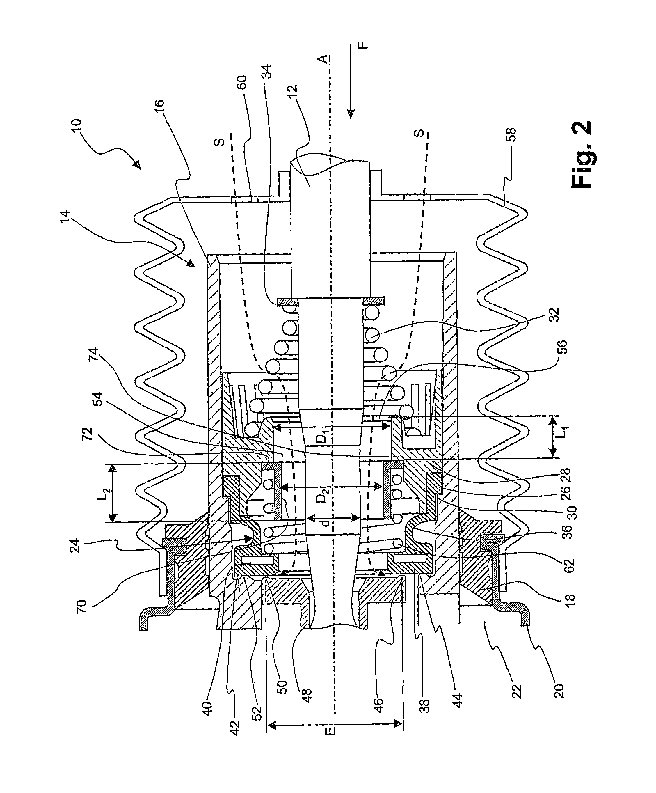
[0024]FIG. 1 shows a detail of a vacuum brake booster according to the invention in an axis-containing longitudinal sectional view, and designated generally by 10. This vacuum brake booster comprises a force input member 12, which at its right-hand end in FIG. 1 faces a connection mechanism, by which it is coupled or can be coupled with a brake pedal. At its left-hand end in FIG. 1, the force input member 12 faces in the direction of a brake master cylinder arrangement (not shown). A control valve 14 is arranged in the vacuum brake booster 10 around the force input member 12. This control valve comprises a control valve housing 16, which is displaceably guided in a brake booster housing 20 in a sealing manner via a seal 18. Arranged in this brake booster housing 20 is a chamber arrangement, which has, in a manner known per se, a working chamber 22 and a vacuum chamber (not shown), the working chamber and the vacuum chamber being separated from one another via a moveable wall (not sh...


PUM


Abstract

A vacuum brake servo includes a force input element, a control valve actuated by the force input element, a vacuum chamber connected to a vacuum source, and an operating chamber which, depending on the actuation of the force input element, can be connected to either the vacuum chamber or the surrounding atmosphere. The control valve has a control piston that can be actuated by the force input element and, together with a valve element, forms a seal seat having a seal seat diameter between the operating chamber and the surrounding atmosphere. In the area close to the seal seat, a guide channel is provided. When the seal seat is opened, air from the surrounding atmosphere flows into the operating chamber. The guide channel extends axially with a constant flow diameter over a predetermined length, wherein the flow diameter is less than or equal to the seal seat diameter.

Description

CROSS-REFERENCE TO RELATED APPLICATIONS[0001]This application is a national stage of International Application No. PCT / EP2010 / 006447 filed Oct. 21, 2010, which claimed priority to German Patent Application No. 10 2009 051 236.5 filed Oct. 29, 2009, the disclosures of which are incorporated herein by reference.BACKGROUND OF THE INVENTION[0002]The present invention relates to a vacuum brake booster for a motor vehicle brake system comprising a rod-like force input member, which is coupled or can be coupled with a brake pedal, a control valve, which can be actuated by means of the force input member, a chamber arrangement having a vacuum chamber, which is connectable to a vacuum source, as well as a working chamber, which is, in accordance with the actuation of the force input member, selectively connectable to the vacuum chamber and to the surrounding atmosphere, wherein the control valve has a control piston actuatable by means of the force input member, which control piston forms to...

Claims


Application Information

Patent Timeline
Patent Type & Authority Patents(United States)
IPC IPC(8): B60T13/57
CPCB60T13/57
Inventor CALVO MARTINEZ, JOSE MANUELSPARFELD, JENSKNIGGE, DETLEVZINNKANN, ULRICH
Owner LUCAS AUTOMOTIVE GMBH
Learn More