Electric machine having magnetic poles including a primary magnet and auxiliary magnets

a technology of magnetic poles and electric machines, which is applied in the direction of dynamo-electric machines, electrical apparatus, dc commutators, etc., can solve the problems of low material utilization efficiency and complicated manufacture of large arcuate magnets, and achieve the effect of improving material utilization efficiency and being easy to manufactur

Inactive Publication Date: 2016-02-16
JOHNSON ELECTRIC SA
View PDF32 Cites 0 Cited by
  • Summary
  • Abstract
  • Description
  • Claims
  • Application Information

AI Technical Summary

Benefits of technology

[0005]Hence there is a desire for an electric machine having an improved stator using magnets which are easier to manufacture and with a higher efficiency of material usage.

Problems solved by technology

However, the manufacture of large arcuate magnets is complicated.
Thus there is a lot of material wastage plus there are breakages when cutting the magnets resulting in a low efficiency of material usage.

Method used


Image

  • Electric machine having magnetic poles including a primary magnet and auxiliary magnets
  • Electric machine having magnetic poles including a primary magnet and auxiliary magnets
  • Electric machine having magnetic poles including a primary magnet and auxiliary magnets

Examples


first embodiment

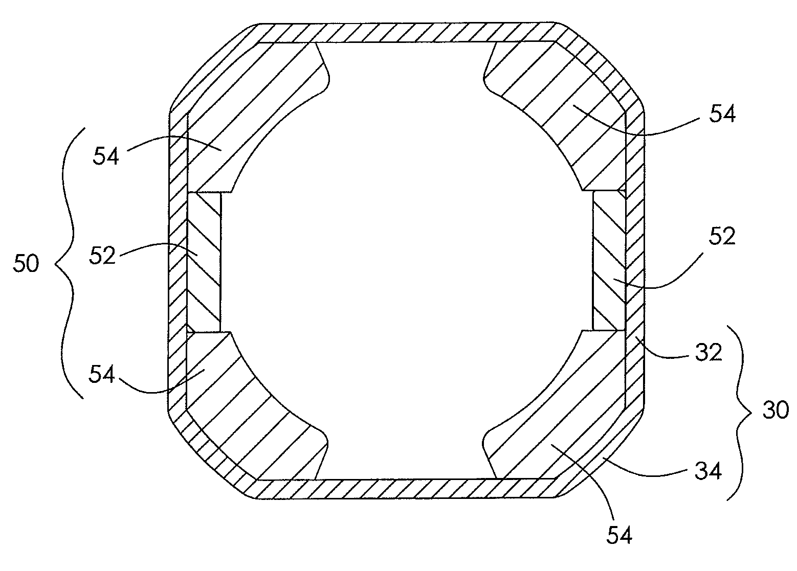
[0023]FIG. 1 is a schematic illustration of a stator of an electric machine in accordance with the present invention. The electric machine may be an electric motor which converts electrical energy to mechanical energy or an electric generator which converts mechanical energy to electrical energy. The stator comprises a housing 30 and a pair of magnetic poles 50 formed by magnets 52, 54 fitted to an inner surface of the housing 30. The magnets 52, 54 are polarized in radial directions of the housing 30. Thus the stator may be described as a two pole stator.

[0024]Preferably, the housing 30 has a square cross section and comprises four side portions 32 and four connecting portions 34 each of which connects two adjacent side portions 32. Preferably, the inner surfaces of the side portions 32 are flat while the inner surfaces of the connecting portions 34 are curved. The thickness of the housing may be uniform or non-uniform.

[0025]Each magnetic pole 50 is formed from a plurality of separ...

third embodiment

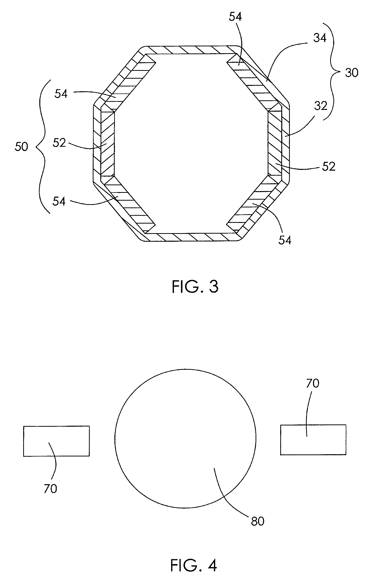
[0030]FIG. 3 shows a stator in accordance with the present invention. The inner surfaces of the side portions 32 and connecting portions 34 of the housing 30 are substantially flat. Each magnetic pole 50 comprises three flat magnets 52, 54 respectively installed at one side portion 32 and two adjacent connecting portions 34. Preferably, all magnets 52, 54 have the same structure and can be made of the same material by the same tool, which results in high efficiency of material usage and low cost. The magnets 52, 54 may be made of ferrite or rare-earth material. Preferably, each of the magnets has a rectangular cross section.

[0031]FIG. 4 is a schematic illustration of a commutation arrangement of the electric machine. The stator 10 further comprises two brushes 70 configured to slidably contact a commutator 80 of the rotor. The two brushes 70 are respectively disposed at opposite sides of the commutator 80 with an angle of 180 mechanical degrees.

[0032]In the present invention, each m...


PUM


Abstract

An electric machine has a stator and a rotor. The stator has a housing and at least one pair of magnetic poles. Each magnetic pole has a primary magnet and two auxiliary magnets disposed on respective sides of the primary magnet. All of the magnets are disposed on an inner surface of the housing. All the magnets of a magnetic pole have the same polarity.

Description

CROSS REFERENCE TO RELATED APPLICATIONS[0001]This non-provisional patent application claims priority under 35 U.S.C. §119(a) from Patent Application No. 201010130858.1 filed in The People's Republic of China on Mar. 22, 2010.FIELD OF THE INVENTION[0002]This invention relates to an electric motor and in particular, to an electric machine with a permanent magnet stator having magnetic poles comprising a plurality of magnets.BACKGROUND OF THE INVENTION[0003]Japanese Published Patent Application No 10-201206 shows a stator for an electric motor. The stator comprises a housing with two arcuate sides and two magnetic poles. Each magnetic pole is composed of one large arcuate magnet which is fixed to an inner surface of a corresponding arcuate side of the housing.[0004]However, the manufacture of large arcuate magnets is complicated. The arcuate magnets are formed as rectangular magnets which are then cut to shape. Thus there is a lot of material wastage plus there are breakages when cutti...

Claims


Application Information

Patent Timeline
Patent Type & Authority Patents(United States)
IPC IPC(8): H02K23/04
CPCH02K23/04
Inventor JIANG, MAO XIONGLI, YUEZHAO, JIANLI, YONGGUO, YU HONG
Owner JOHNSON ELECTRIC SA
Why Eureka
Try Eureka