
Electronic device and control method thereof

a technology of electronic devices and control methods, applied in the direction of basic electric elements, greenhouse gas reduction, transportation and packaging, etc., can solve the problems of increasing hardware cost and power consumption, affecting the operation generating significant errors of ambient light sensors, so as to reduce the number of elements, hardware cost, and power consumption of the device.

Active Publication Date: 2016-02-16
COMPAL ELECTRONICS INC
View PDF11 Cites 2 Cited by
  • Summary
  • Abstract
  • Description
  • Claims
  • Application Information

AI Technical Summary

Benefits of technology

This solution reduces the number of elements, hardware costs, and power consumption while minimizing errors in light source adjustments, enhancing operational functionalities and precision in controlling light source parameters.

Problems solved by technology

However, to attain the above adjustment and application of the light source at the same time, an ambient light sensor and a solar cell should be both configured in an electronic device, which leads to an increment of the hardware cost and the power consumption.
Additionally, in terms of a backlight plate, OLED, and an electronic paper product with small sizes, there exist limitations in the application of an ambient light sensor.
Moreover, during the usage of the ambient light sensor, different placement positions may cause the ambient light sensor to generate significant errors, wherein the maximum error is, for example, + / −25%.

Method used


Image

  • Electronic device and control method thereof
  • Electronic device and control method thereof
  • Electronic device and control method thereof

Examples


Embodiment Construction

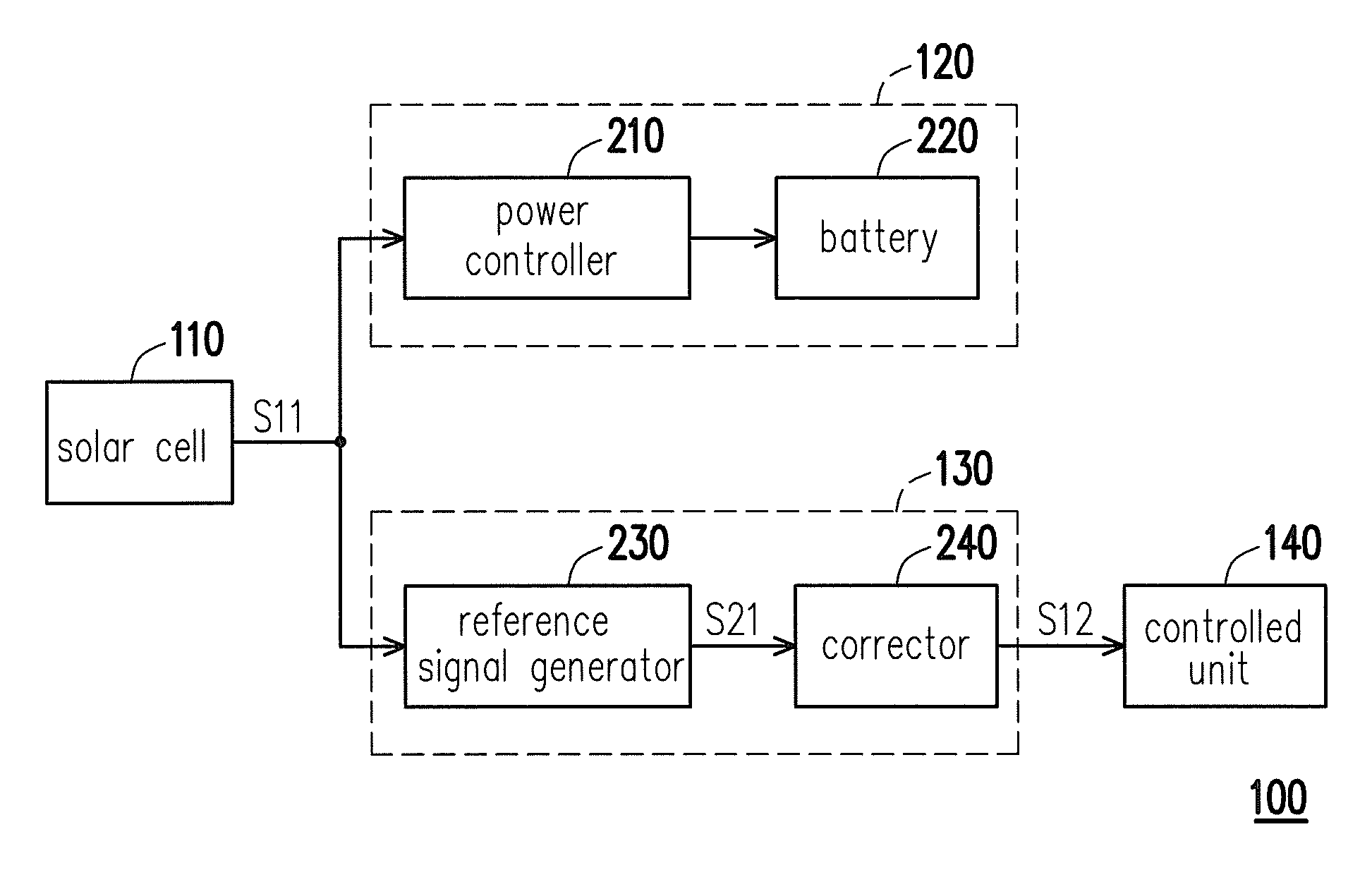
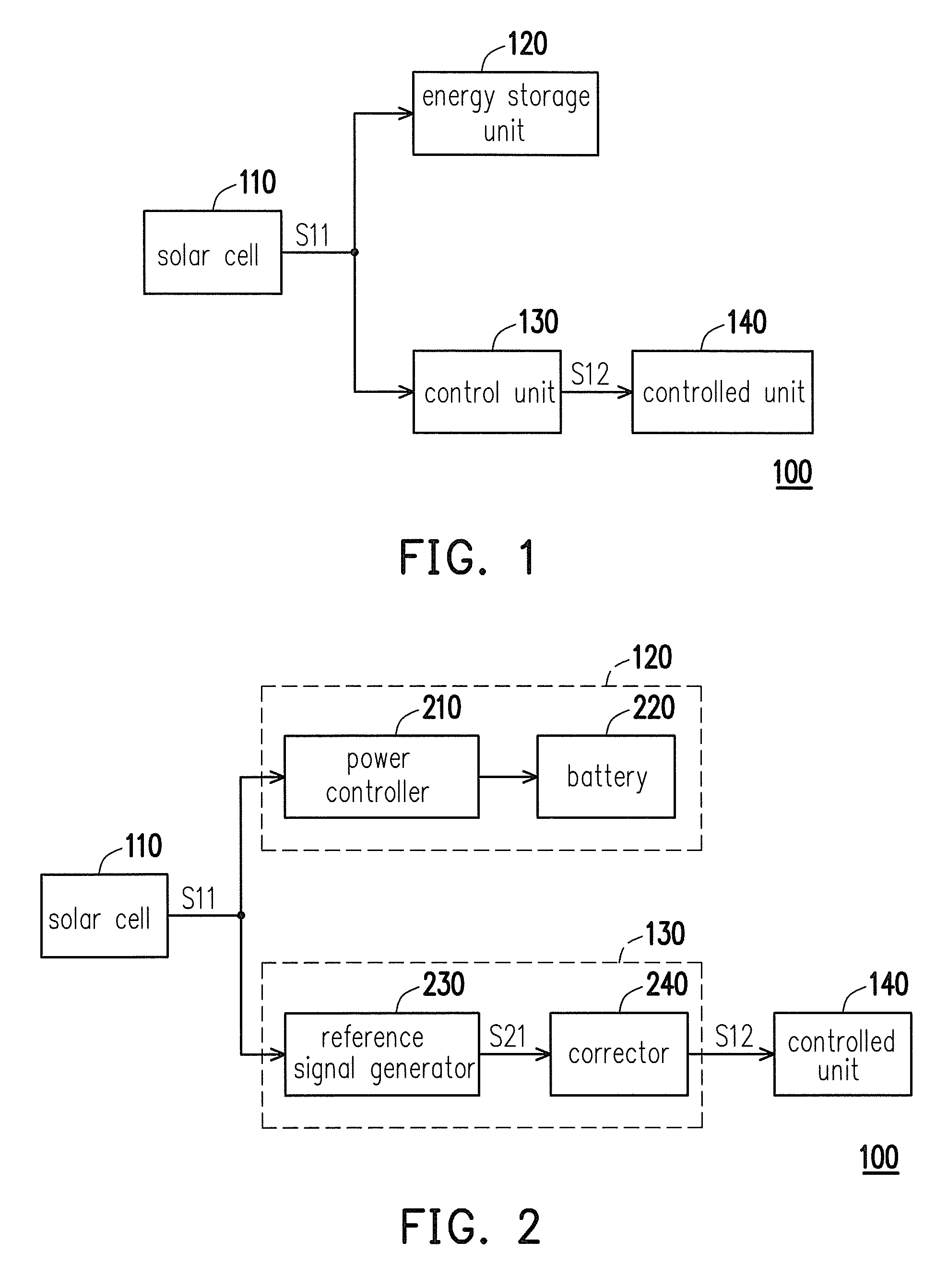
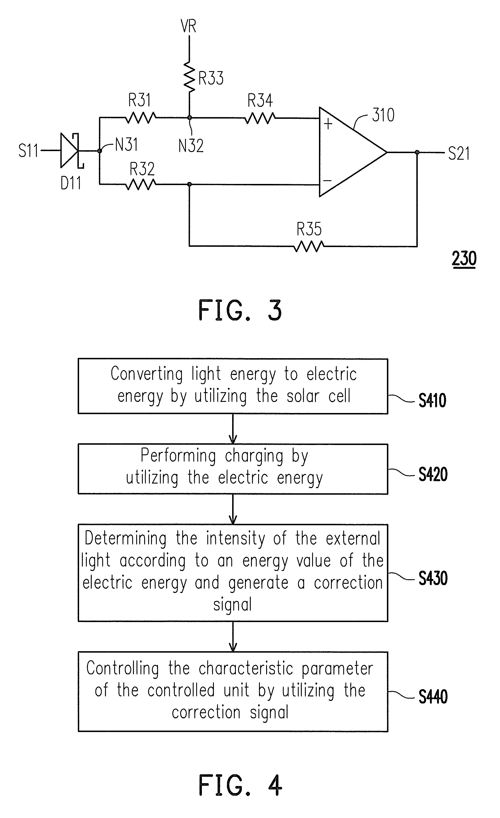
[0022]FIG. 1 is a block diagram of an electronic device in accordance with an embodiment in the present invention. Referring to FIG. 1, the electronic device 100 includes a solar cell 110, an energy storage unit 120, a control unit 130, and a controlled unit 140, wherein the energy storage unit 120 and the control unit 130 are electrically connected to the solar cell 110, and the controlled unit 140 are electrically connected to the control unit 130.

[0023]In the overall operation, the solar cell 110 may convert light energy to electric energy S11, and the energy storage unit 120 may perform charging by using the electric energy S11 from the solar cell 110, wherein the electric energy S11 is a charging current. For example, at the moment that the solar cell 110 is illuminated by a light source, it generates a corresponding current, wherein the generated current is proportional to the intensity of the light energy. Correspondingly, the energy storage unit 120 may perform charging by u...


PUM


Abstract

An electronic device including a solar cell, an energy storage unit, a control unit, and a controlled unit is provided. The solar cell converts light energy to electric energy. The energy storage unit performs charging by the electric energy. The control unit determines the intensity of the light energy according to an energy value of the electric energy and generates a correction signal accordingly, wherein the energy value is a current value or a voltage value. The controlled unit controls a characteristic parameter according to the correction signal.

Description

CROSS-REFERENCE TO RELATED APPLICATION[0001]This application claims the priority benefit of Taiwan application serial no. 101134171, filed on Sep. 18, 2012. The entirety of the above-mentioned patent application is hereby incorporated by reference herein and made a part of this specification.FIELD OF THE INVENTION[0002]The present invention generally relates to an electronic device and a control method thereof, in particular, to an electronic device with a solar cell and a control method thereof.DESCRIPTION OF RELATED ART[0003]An electronic device may detect the intensity of light source, which may further be a reference of the light adjustment, through a disposition of an ambient light sensor (ALS). For example, a display panel of an electronic device may adjust the brightness of its backlight source based on the electric signal generated by the ambient light sensor. By that means, the display panel may adjust the backlight brightness in accordance with the intensity of light sourc...

Claims


Application Information

Patent Timeline
Patent Type & Authority Patents(United States)
IPC IPC(8): H05B37/02H02J7/00H05B37/00H02J7/35H01L31/053
CPCH05B37/02H01L31/053H02J7/0052H05B37/00H02J7/35Y02E10/50Y02E70/30H05B47/10
Inventor LIN, YI-HSUNFU, FENG-WEN
Owner COMPAL ELECTRONICS INC
Learn More