Neutron spectrometer

a technology of neutron spectrometer and neutron beam, which is applied in the field of neutron spectrometer, can solve the problems of significant hazard, source intensity, and significant hazard, and achieve the effect of preparing to couple into wavelength-shifting light-guides

Inactive Publication Date: 2016-02-23
SYMETRICA
View PDF9 Cites 1 Cited by
  • Summary
  • Abstract
  • Description
  • Claims
  • Application Information

AI Technical Summary

Benefits of technology

[0007]The neutron spectrometer is in the form of a series of thermal-neutron detectors interleaved between a neutron moderating material in such a way that the number of events detected in each layer of thermal-neutron detector can be recorded. The number of detected events can provide the ratio of the probability that incident neutrons have thermalised at different depths in the moderating material layers, which can provide sufficient information to distinguish between common types of neutron sources.
[0009]Each of the first and second conversion screens may comprise a substrate having the neutron absorbing material and the phosphor material in a powdered form in a binding material thereon. This provides a simple way of producing the screens.
[0016]The conversion screens and wavelength-shifting light-guides may be in loose optical contact. This enables the optical photons from the phosphor material in the conversion screens to readily couple into the wavelength-shifting light-guides.

Problems solved by technology

One of the most challenging tasks that have been set for radiation detectors in the field of Homeland Security is the reliable detection of nuclear weapons and special nuclear materials which may be concealed in cargo crossing international borders.
Whilst such sources of neutron radiation can be controlled, other neutron sources are based on radioactive materials which can provide a significant hazard.
These sources can be intense and represent a significant hazard in their own right, particularly if they are combined with explosives to provide a so-called “dirty bomb”.

Method used


Image

  • Neutron spectrometer
  • Neutron spectrometer
  • Neutron spectrometer

Examples


Embodiment Construction

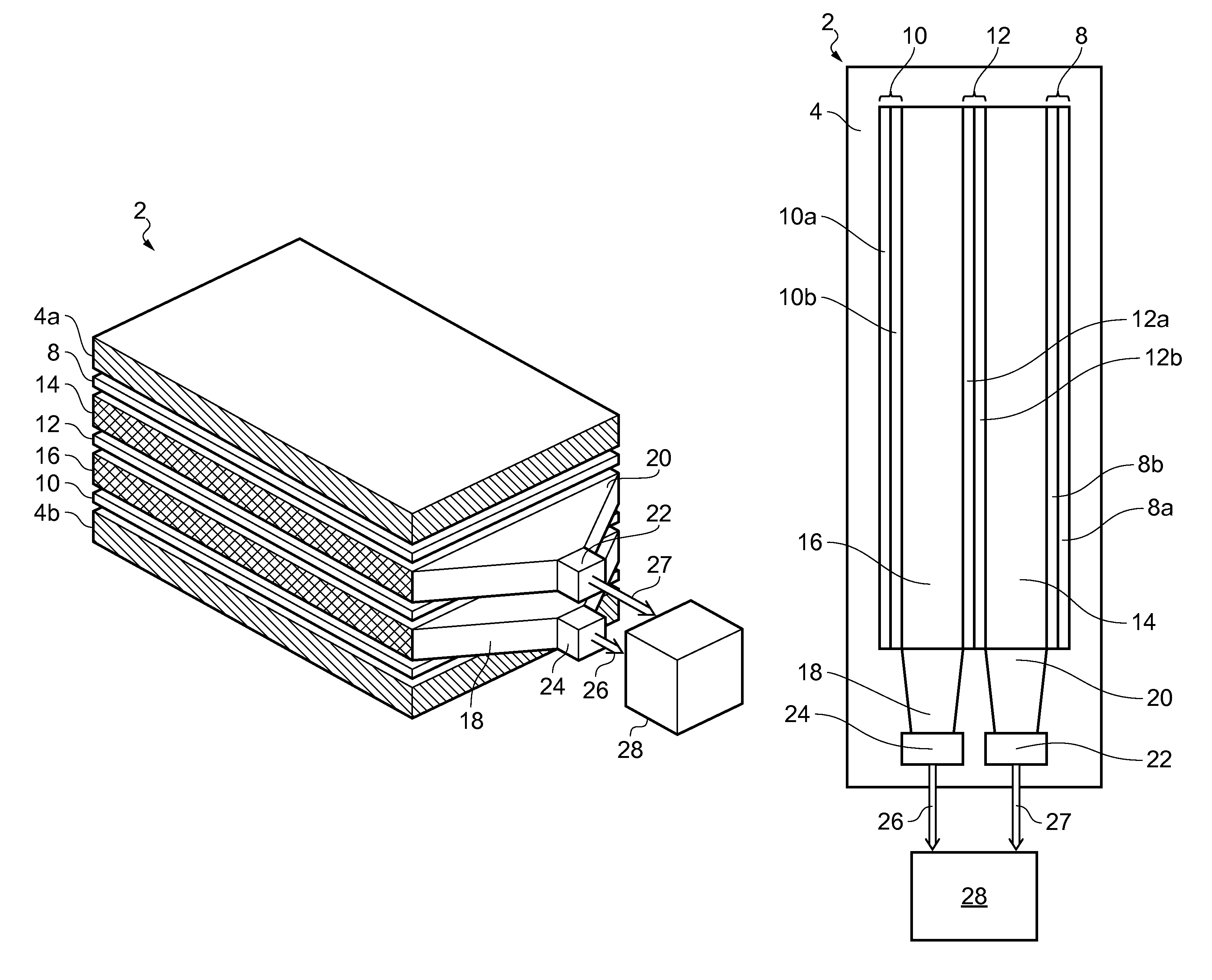
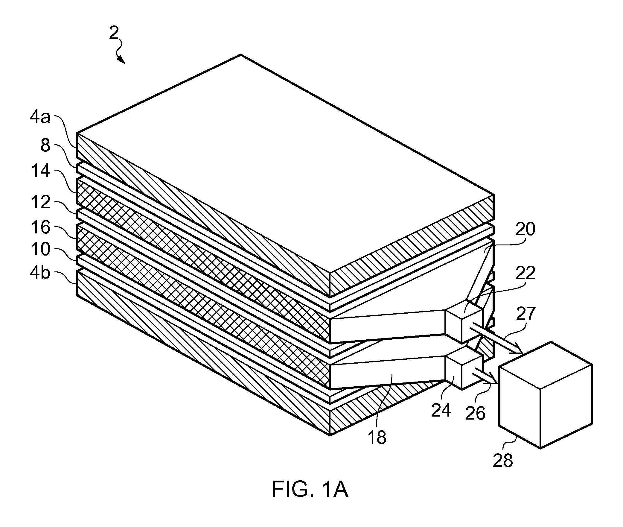
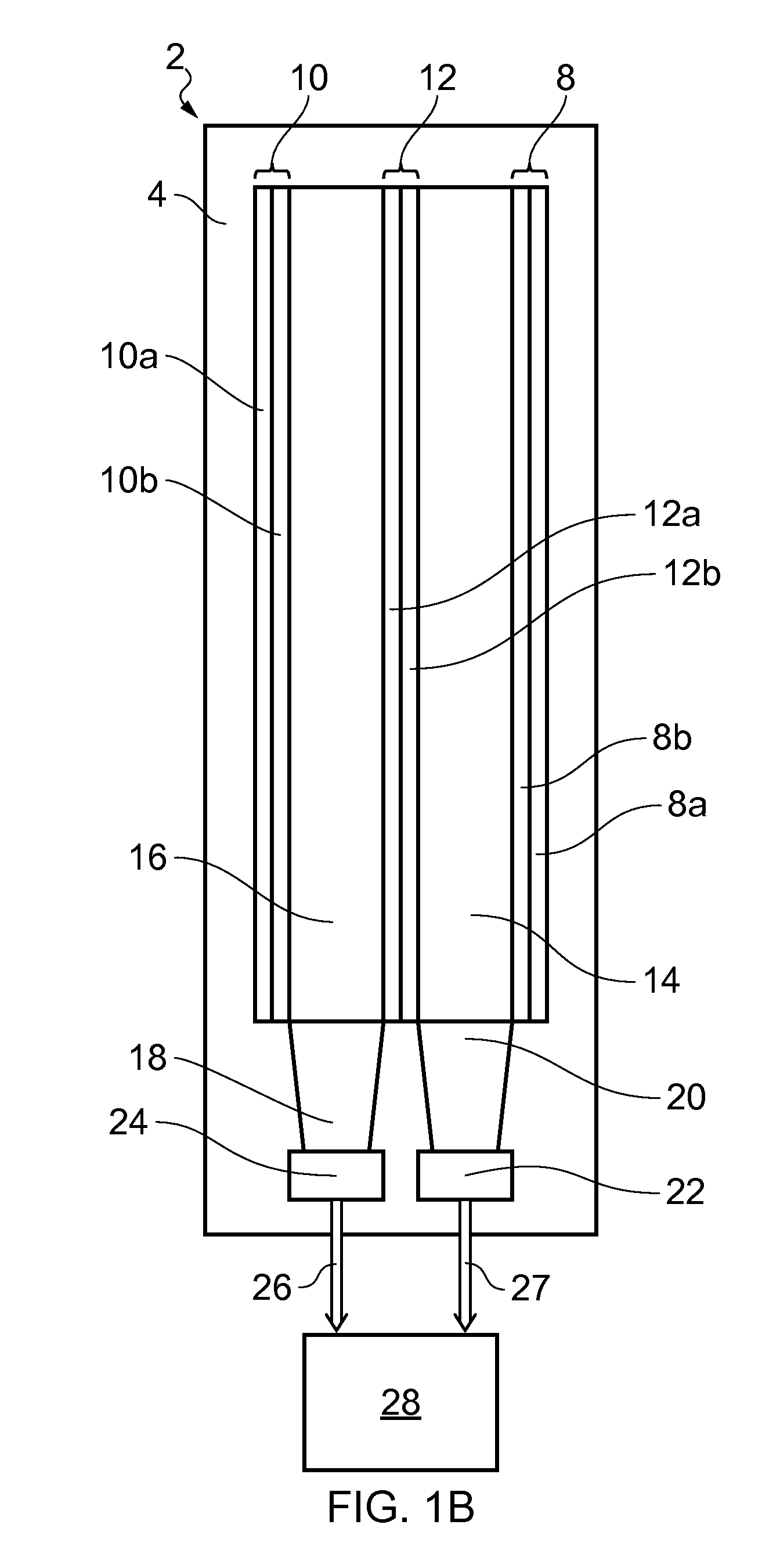
[0024]FIGS. 1A and 1B schematically show a neutron spectrometer 2 according to an embodiment of the invention in perspective and side views. The neutron detector 2 has a generally layered structure. Various layers of the detector 2 are shown separated from one another in FIG. 1A for ease of representation. In practice the different layers will generally be in contact with one another, e.g. loose optical contact.

[0025]The neutron spectrometer comprises first, second, and third neutron absorbing conversion screens 8, 12, 10. Separating the first and second conversion screens 8, 12 is a first wavelength-shifting light-guide 14 and separating the second and third conversion screens 10, 12 is a second wavelength-shifting light-guide 16. Each of the first and second wavelength-shifting light-guides 14, 16 is in the form of a plastic scintillator plank (or sheet). Thus the first wavelength-shifting light-guide 14 is flanked by the first and second conversion screens 8, 12 and, the second w...


PUM


Abstract

A neutron spectrometer is described. The spectrometer includes a first conversion screen (8) comprising a neutron absorbing material and a phosphor material, a first wavelength-shifting light-guide (14) arranged to receive photons from the phosphor material of the first conversion screen and generate wavelength-shifted photons therefrom and a first photodetector (22) optically coupled to the first wavelength-shifting light-guide and arranged to detect the wave-length-shifted photons. The spectrometer further includes a second conversion screen (12) comprising a neutron absorbing material and a phosphor material, a second wavelength-shifting light-guide (16) arranged to receive photons from the phosphor material of the second conversion screen and generate wavelength-shifted photons there-from, and a second photodetector (24) optically coupled to the second wavelength-shifting light-guide and arranged to detect the wave-length-shifted photons. A neutron moderator material is arranged between the first and second conversion screens to moderate neutrons.

Description

BACKGROUND ART[0001]The invention relates to neutron spectrometers.[0002]One of the most challenging tasks that have been set for radiation detectors in the field of Homeland Security is the reliable detection of nuclear weapons and special nuclear materials which may be concealed in cargo crossing international borders. Whilst roughly 1 to 2% of all cargo vehicles carry innocent radioactive materials, typically one in 104 of these are found to be carrying a neutron source. Neutron sources find applications for example in the oil and gas exploration industry, soil moisture gauges, materials analysis and radiography.[0003]A neutron source may be provided by accelerating deuterium ions towards an electrode that has been loaded with tritium. Whilst such sources of neutron radiation can be controlled, other neutron sources are based on radioactive materials which can provide a significant hazard. For example, intense alpha-particle emitters such as Americium-241 or Plutonium-238 are oft...

Claims


Application Information

Patent Timeline
Patent Type & Authority Patents(United States)
IPC IPC(8): G01T1/20G01T3/00G01T3/06G01V5/00
CPCG01T3/001G01T3/06G01V5/0091G01T3/065
Inventor RAMSDEN, DAVIDGILES, CALVIN
Owner SYMETRICA
Why Eureka
Try Eureka