
Electron gun, method of controlling same, and electron beam additive manufacturing machine

a technology of electron beam and additive manufacturing machine, which is applied in the direction of electrodes, discharge tubes/lamp details, manufacturing tools, etc., can solve the problems of insufficient beam focus, inability to control the beam current using the current-limiting aperture, and damage to the aperture, etc., and achieve the effect of keeping the brightness of the electron beam constan

Active Publication Date: 2016-02-23
JEOL LTD
View PDF4 Cites 2 Cited by
  • Summary
  • Abstract
  • Description
  • Claims
  • Application Information

AI Technical Summary

Benefits of technology

The present invention aims to provide an electron gun that maintains the brightness of the electron beam without using a current-limiting aperture. The invention uses a control electrode to control the electric field strength at the tip of the cathode, ensuring a constant brightness of the electron beam. This technology prevents a drop in brightness, which is often experienced in conventional electron guns.

Problems solved by technology

If such a large-power electron beam irradiates the current-limiting aperture, the aperture may be damaged.
This makes it impossible to control the beam current using the current-limiting aperture.
As a result, the beam cannot enough be focused.
Consequently, it is difficult to fabricate an object accurately.
This may result in the sample being molten nonuniformly.

Method used


Image

  • Electron gun, method of controlling same, and electron beam additive manufacturing machine
  • Electron gun, method of controlling same, and electron beam additive manufacturing machine
  • Electron gun, method of controlling same, and electron beam additive manufacturing machine

Examples


Embodiment Construction

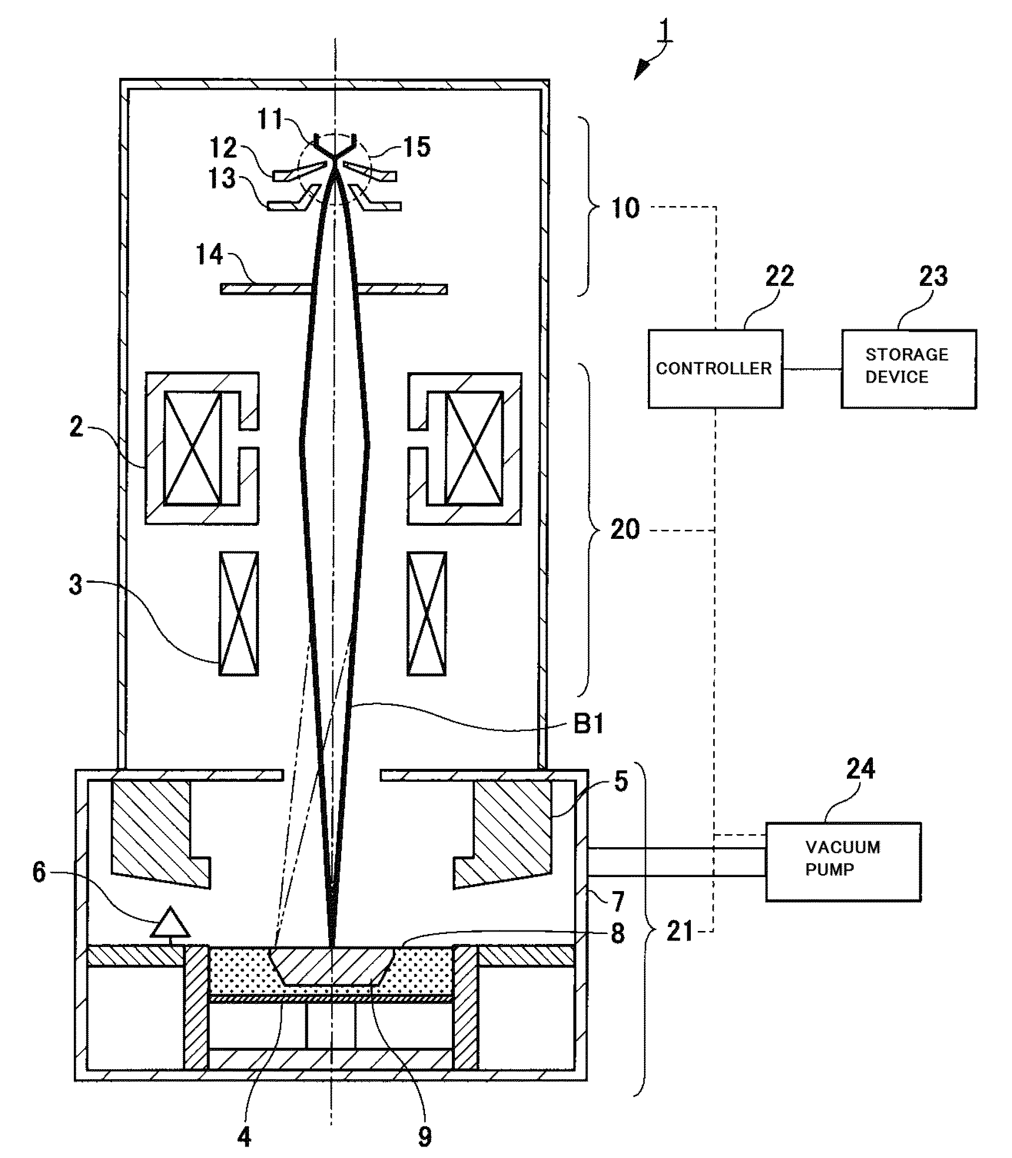
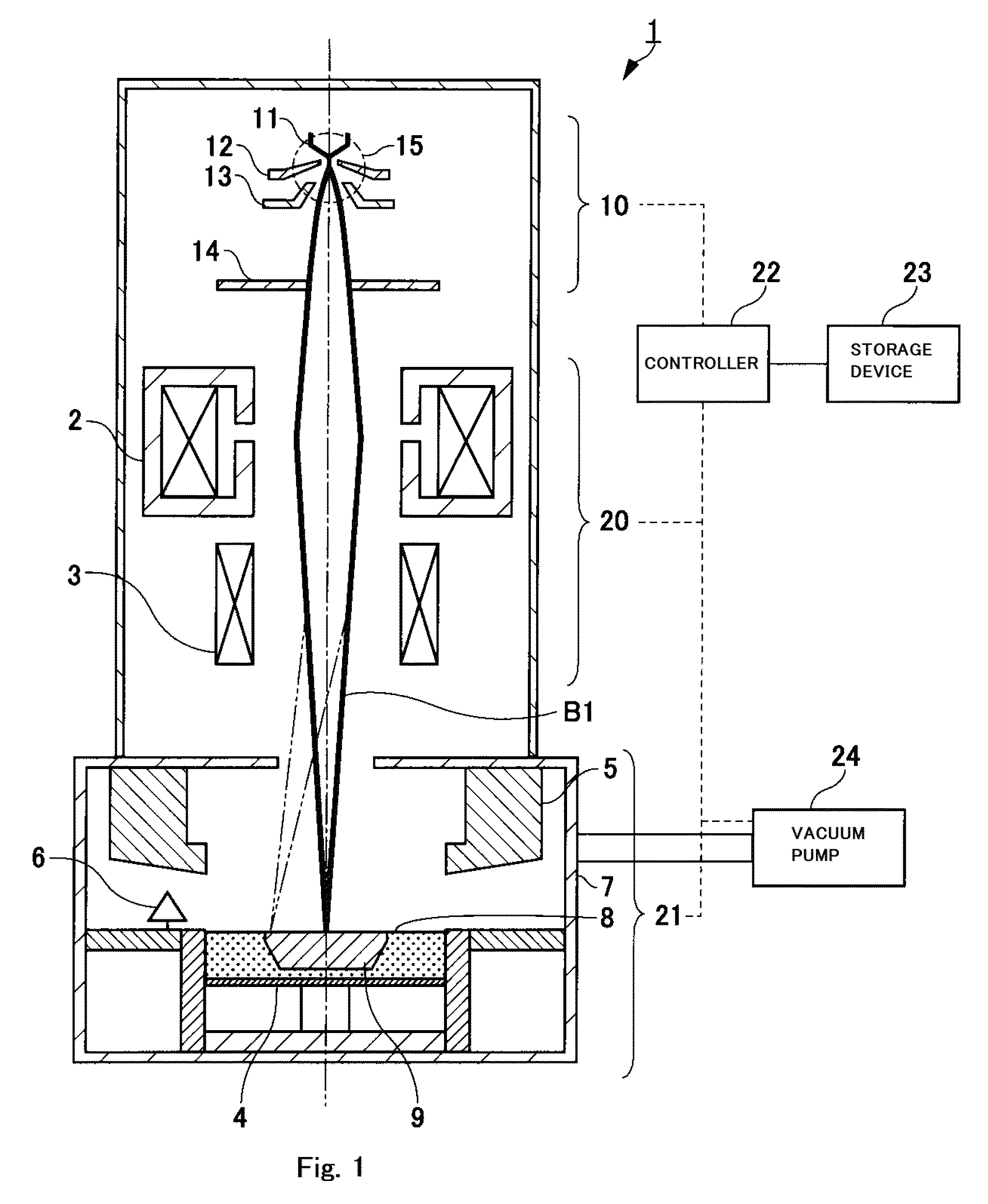
[0023]An electron gun, a method of controlling it, and an electron beam additive manufacturing (AM) machine associated with one embodiment of the present invention are hereinafter described with reference to the accompanying drawings. In this electron beam AM machine, there is achieved a method of controlling an electron gun wherein the electron gun is controlled such that the brightness of the electron beam is kept constant. In the present specification and drawings, components which are substantially identical in function or configuration are indicated by the same reference numerals and so a repeated description thereof is omitted.

[0024]FIG. 1 shows the configuration of an electron beam additive manufacturing machine employing a layer manufacturing method, the machine being indicated by reference numeral 1. This additive manufacturing (AM) machine 1 can directly fabricate a complex part from data created by a three-dimensional CAD (computer-aided design) in the same way as a conve...


PUM

PropertyMeasurementUnit
tilt angleaaaaaaaaaa
diameteraaaaaaaaaa

Abstract

There is disclosed a method of controlling an electron gun without causing decreases in brightness of the electron beam if a current-limiting aperture cannot be used. The electron gun (10) has a cathode (11), a Wehnelt electrode (12), a control electrode (13), an anode (14), and a controller (22). The Wehnelt electrode (12) has a first opening (12c) in which the tip of the cathode is inserted, and focuses thermal electrons emitted from the tip of the cathode (11). The thermal electrons emitted from the tip of the cathode (11) are caused to pass into a second opening (13c) by the control electrode (13). The anode (14) accelerates the thermal electrons emitted from the cathode (11) such that the thermal electrons passed through the second opening (13c) pass through a third opening (14b) and impinge as an electron beam (B1) on a powdered sample (8). The controller (22) sets the bias voltage and the control voltage based on combination conditions of the bias voltage and control voltage to maintain the brightness of the beam constant.

Description

BACKGROUND OF THE INVENTION[0001]1. Field of the Invention[0002]The present invention relates to an electron gun used when a three-dimensional (3D) object is fabricated by stacking thin layers of a powdered sample on top of each other on a support stage. The invention also relates to a method of controlling this electron gun. Furthermore, the invention relates to an electron beam additive manufacturing machine.[0003]2. Description of Related Art[0004]There is a widely known additive manufacturing machine that builds a three-dimensional object by spreading resinous powder tightly over the whole support stage to form a powder layer, irradiating the powder layer with laser light to melt the resinous powder, allowing the molten powder to solidify, and stacking layers of such solidified resinous powder on top of each other. In recent years, additive manufacturing machines using an additive layer manufacturing method for fabricating a three-dimensional object by spreading a powder sample ...

Claims


Application Information

Patent Timeline
Patent Type & Authority Patents(United States)
IPC IPC(8): H01J29/58H01J3/08H01J3/02H01J37/305B23K15/00B23K15/06B33Y30/00H01J37/063
CPCH01J3/08B23K15/002B23K15/0026B23K15/0086B23K15/06H01J3/02H01J3/024H01J3/027H01J37/063H01J37/305B33Y30/00H01J2237/065H01J2237/06308H01J2237/3128Y02P10/25B22F12/41B22F10/28B22F10/36B22F12/44
Inventor SATOH, TAKASHI
Owner JEOL LTD
Learn More