Magnetic structure for circular ion accelerator

a circular ion accelerator and magnet structure technology, applied in the direction of accelerators, magnetic resonance accelerators, electrical devices, etc., can solve the problems of increasing the magnetic stray field, reducing the efficiency of the yoke structure, and prolonging the down time period of the cyclotron operation. , to achieve the effect of increasing the refrigeration capacity

Active Publication Date: 2016-02-23
ION BEAM APPL
View PDF15 Cites 18 Cited by
  • Summary
  • Abstract
  • Description
  • Claims
  • Application Information

AI Technical Summary

Benefits of technology

[0012]Preferably two dry cryocooler units are received in the same opening in the return yoke, wherein they are preferably superimposed at a same radial position. Indeed, by superimposing two cryocooler units at the same radial position with respect to the return yoke, the return flux of the magnetic field remains the same when compared to the use of a single cryocooler unit at the same radial position and hence there is no need to increase the diameter of the cyclotron to compensate for the loss of magnetic flux capacity when installing a second cryocooler unit for increasing the refrigeration capacity.

Problems solved by technology

A first disadvantage of the magnetic structure as disclosed in U.S. Pat. No. 7,656,258 resides in the fact that for each cryocooler unit installed in the upper, respectively lower part of the yoke structure, a corresponding hole must be made in a symmetrical way in the opposite lower part, respectively the opposite upper part of the yoke structure.
A great number of holes in the yoke structure also results in a second disadvantage, namely a reduction of the efficiency of the yoke structure and an increase of the magnetic stray field.
A third disadvantage is due to the fact that vertically positioned dry cryocooler units increase the height of the accelerator and hence require a larger building with sufficiently high ceilings to house the cyclotron.
Hence, before opening the cyclotron, it is necessary to first disconnect the vertically arranged cryocooler units from the cold mass structure, which is a major fourth disadvantage.
This fourth disadvantage further results in longer down time periods of cyclotron operation, when the cyclotron must be opened for e.g. maintenance purposes.

Method used


Image

  • Magnetic structure for circular ion accelerator
  • Magnetic structure for circular ion accelerator
  • Magnetic structure for circular ion accelerator

Examples


Embodiment Construction

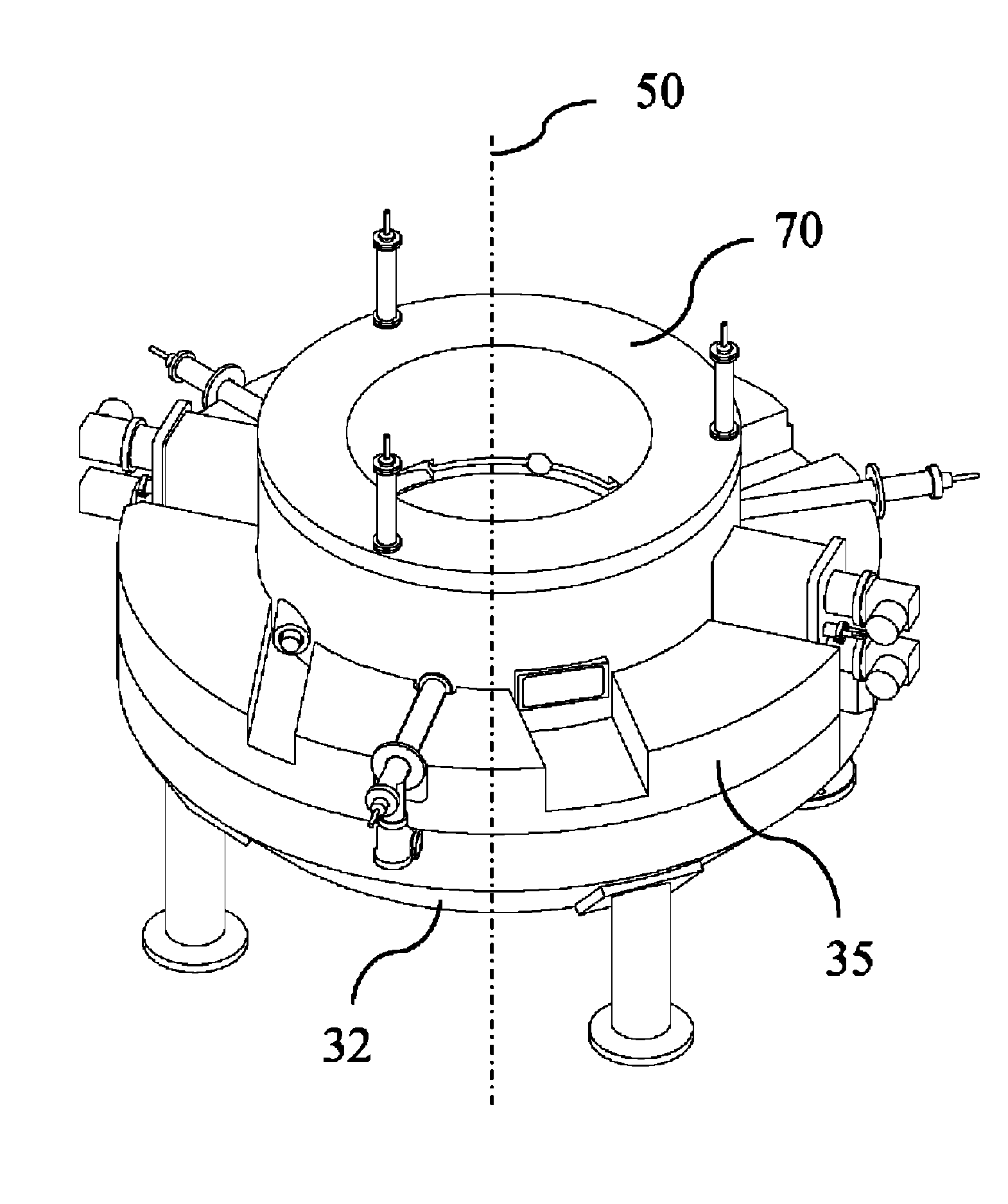
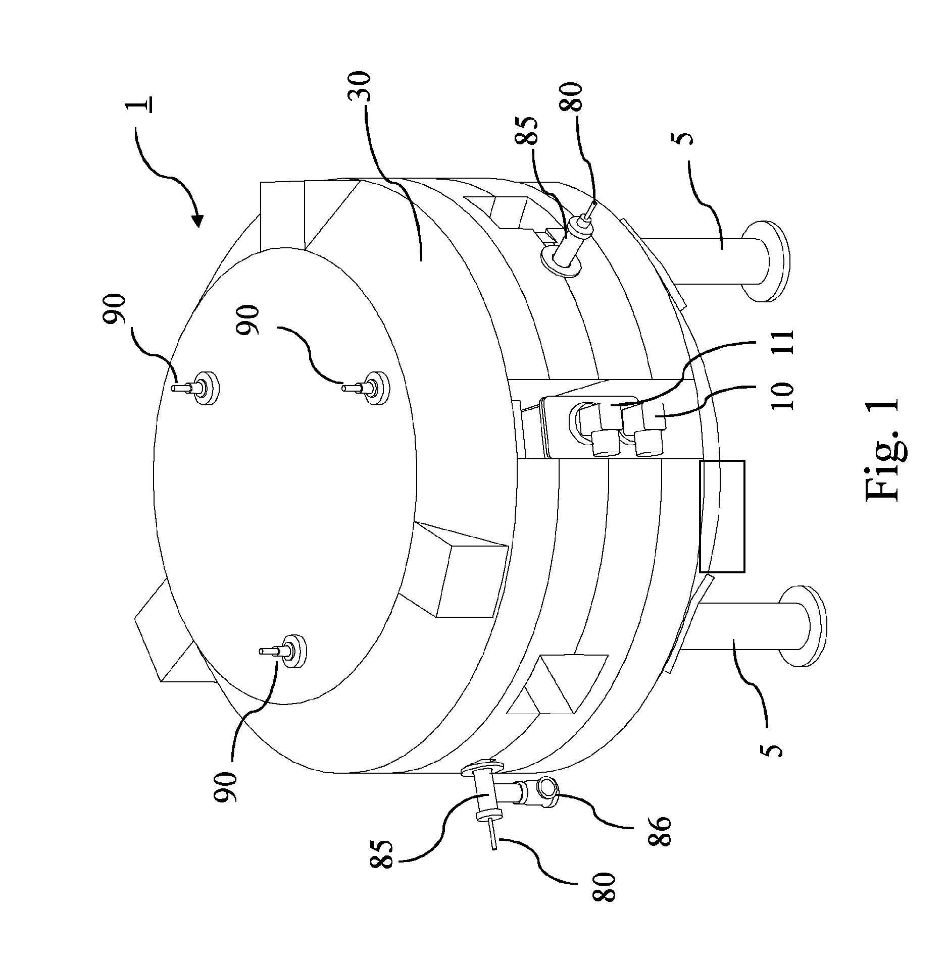
[0028]FIG. 1 shows, as an illustration of the invention, a three dimensional view of a preferred embodiment of a synchrocyclotron 1 comprising a magnetic structure according to the invention. It will be noted that, for the sake of clarity, the representation of the synchrocyclotron 1 is only schematic, and that not all its parts and details are shown. The major part of the magnetic structure that is visible from the outside of the synchrocyclotron is a magnetic yoke structure 30, which is usually made of ferromagnetic iron. The synchrocyclotron with its magnetic structure is supported on the floor by several feet 5.

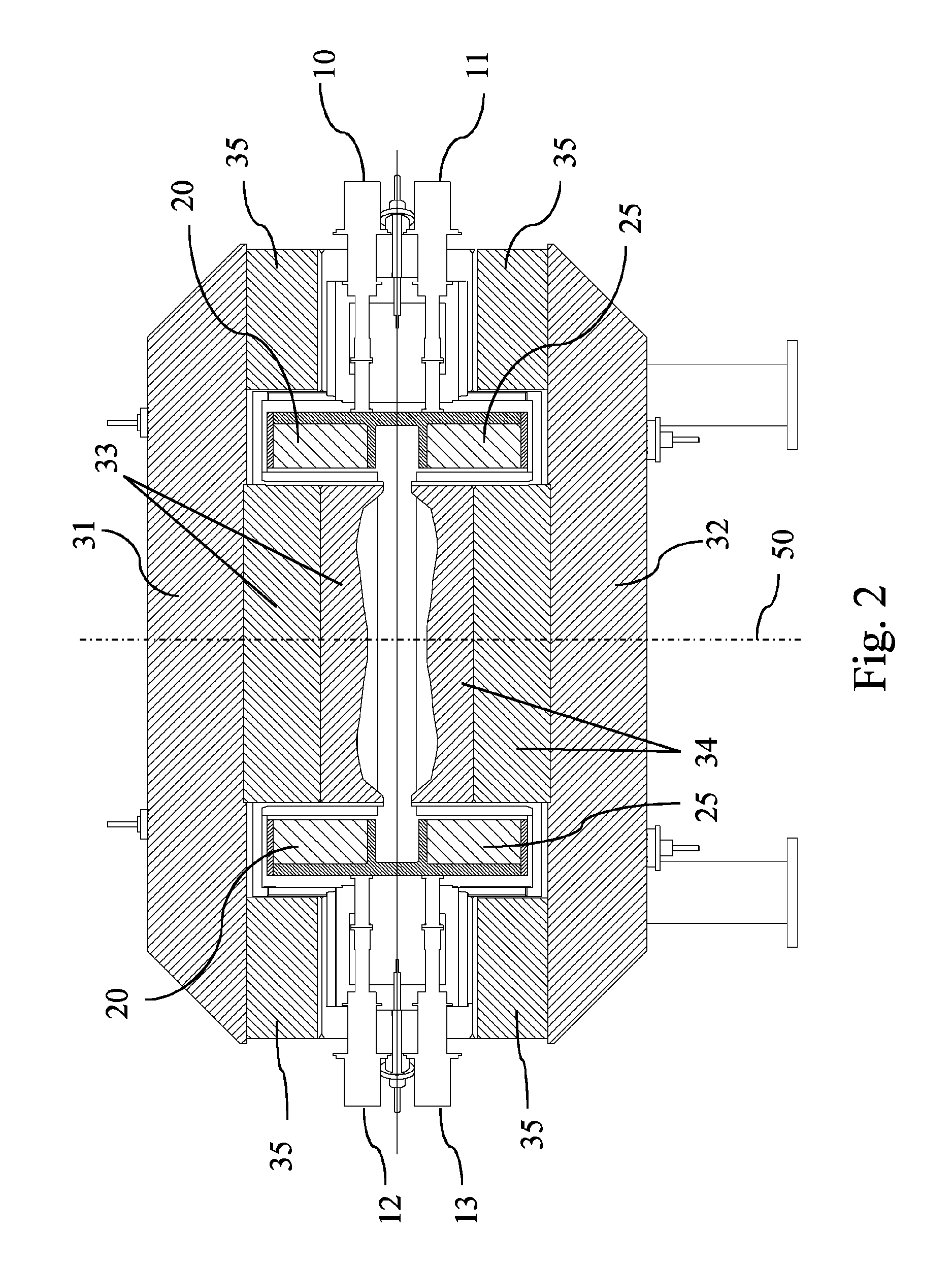
[0029]FIG. 2 is a schematic sectional view illustrating a preferred embodiment of magnetic structure according to the invention. The magnetic structure comprises two circular superconducting magnetic coils 20, 25. These coils have an annular shape and are superimposed symmetrically with regard to a median plane of the synchrocyclotron 1. To fix the ideas, it will be noted...


PUM


Abstract

A magnet structure for use in a circular ion accelerator, such as e.g. a synchrocyclotron comprises a cold-mass structure including superconducting magnetic coils (20, 25), at least one dry cryocooler unit (10, 11, 12, 13) coupled with the cold-mass structure for cooling the latter and a magnetic yoke structure (30) with a return yoke (35) configured radially around said coils (20, 25). The return yoke (35) comprises an opening in which said dry cryocooler unit (10, 11, 12, 13) is received so as to be in thermal contact with said cold-mass structure.

Description

CROSS REFERENCE TO RELATED APPLICATIONS[0001]This application is a national phase application of International Application No. PCT / EP2011 / 068691, filed Oct. 25, 2011, designating the United States and claiming priority to European Patent Application No. 10188946.7, filed Oct. 26, 2010, both of which are incorporated by reference as if fully rewritten herein.TECHNICAL FIELD[0002]The invention generally relates to a circular ion accelerator, more particularly to a superconducting synchrocyclotron. More specifically, the invention relates to a magnet structure for a circular ion accelerator, more particularly to a magnetic structure for a superconducting synchrocyclotron.DESCRIPTION OF PRIOR ART[0003]A typical magnetic structure of a superconducting synchrocyclotron generally comprises a cold-mass structure including at least two superconducting magnetic coils, i.e. magnetic coils which comprise a material that is superconducting below a nominal temperature, and a bobbin associated wit...

Claims


Application Information

Patent Timeline
Patent Type & Authority Patents(United States)
IPC IPC(8): H05H15/00H05H13/02H05H7/04
CPCH05H7/04H05H13/02
Inventor VERBRUGGEN, PATRICKDE NEUTER, SEBASTIENMARABOTTO, ROBERTOCAPELLUTO, ALESSIO
Owner ION BEAM APPL
Why Eureka
Try Eureka