Controllable load distribution system for a vehicle

a technology for distribution systems and vehicles, applied in cycle equipment, transportation and packaging, instruments, etc., can solve the problems of increasing the cost of tires and wheel sets, and increasing the overall cost of rig operation, so as to achieve simple design and construction, reduce the cost of installation, and reduce the cost of production.

Active Publication Date: 2016-03-01
VALVERIDE LLC
View PDF2 Cites 22 Cited by
  • Summary
  • Abstract
  • Description
  • Claims
  • Application Information

AI Technical Summary

Benefits of technology

[0012]The controllable weight distribution system for a vehicle of the present invention addresses the aforementioned needs in the art by allowing the weight load on each axle to be controlled independently and automatically, based on preprogrammed parameters, which may be overridden by an operator. The use of the controllable weight distribution system for a vehicle allows the removal of wheels from one or more axles of the vehicle and controls the maximum weight load on such axle(s) so as not to overload the remaining tires on such axle(s). The controllable weight distribution system for a vehicle is automatic so that once installed and its software appropriately programmed, the system achieves its function without the necessity of operator involvement, although the controllable weight distribution system for a vehicle allows the operator to chan...

Problems solved by technology

Clearly, there is excess tire weight support capacity relative to the allowable load capacity on each axle.
Such extra tires increase the overall costs of rig operation in that the tires and wheel set themselves cost money to purchase and maintain.
Additionally, the additional tires on the rig increase the rolling resistance of the rig which decreases fuel efficiency of the rig.
However, this is not as ea...

Method used


Image

  • Controllable load distribution system for a vehicle
  • Controllable load distribution system for a vehicle
  • Controllable load distribution system for a vehicle

Examples


Embodiment Construction

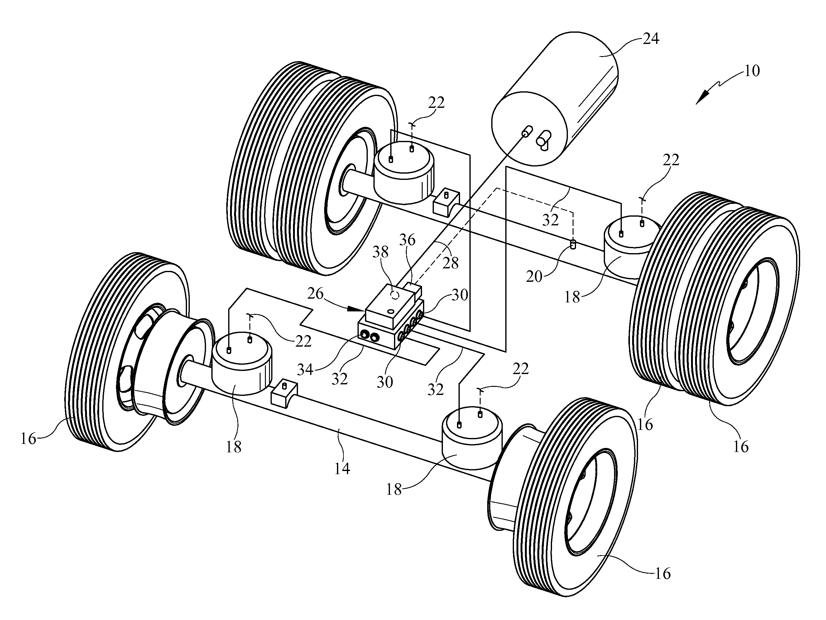
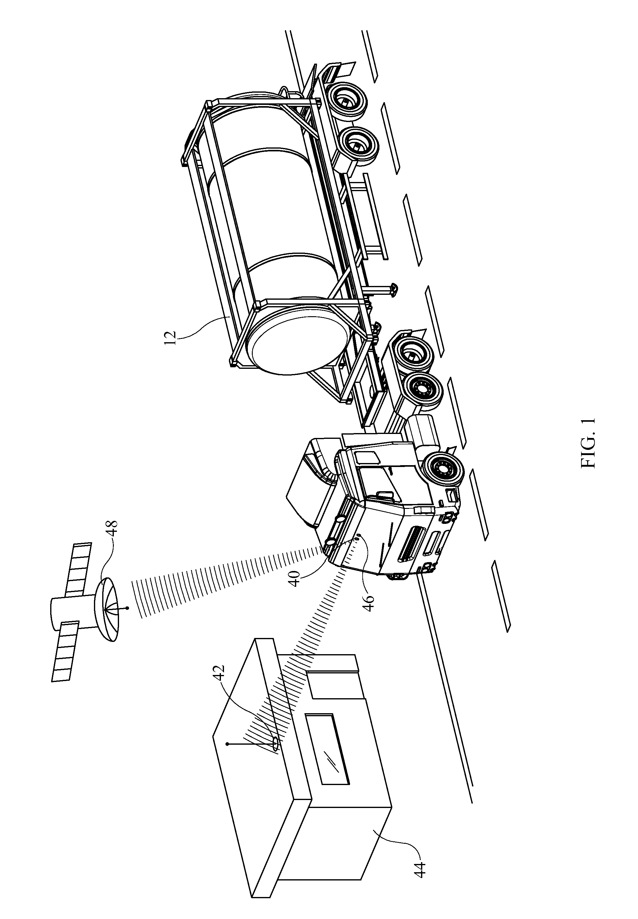
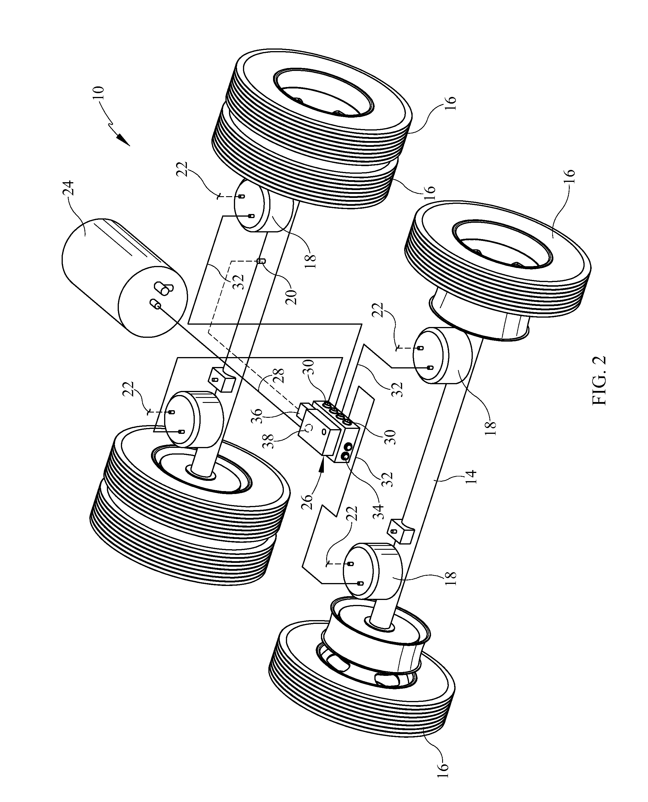
[0017]Referring now to the drawings, it is seen that the controllable weight distribution system for a vehicle of the present invention, generally denoted by reference numeral 10, is installed on a tractor-trailer combination 12, or even a single truck, such as a dump truck, wherein the vehicle at issue has an air bag suspension system. As seen, the vehicle has a series of axles 14 with a set of tires 16 on either side of each axle 14. In a typical modern tractor-trailer combination, there are two tires 16 on the steer axle, a total of eight tires 16 on the drive axle pair (four tires per axle) and a total of eight tires 16 on the tandem axle pair (four tires per axle)—the so-called 18 wheeler. Of course, other combinations are possible such as a tractor that has only a single drive axle or trailers that have a single axle or more than two axles, etc. As seen, each axle 14 has a pair of air bags 18 thereon, one air bag 18 on either side of the axle 14. Each air bag 18, part of the a...


PUM


Abstract

A weight distribution system for dynamically controlling and adjusting the weight load on each axle of a vehicle uses a manifold that is fluid flow disposed between a source of pressured air of the vehicle and the air bags of the vehicle. The manifold allows an individual air bag to be inflated or deflated to a desired pressurization depending on either preprogrammed or user input parameters. By individually controlling the air bags, the system allows the setting of the maximum amount of weight to be borne by a given axle so that tires can be removed from that axle without weight overloading the remaining tires. The system also automatically self-levels the chassis of the vehicle and maintains proper ride height of the vehicle using input from a height sensor located on one of the axles. The system wirelessly communicates, terrestrially or via satellite, its parameters to roadway officials to verify that the vehicle is in compliance with weight loading requirements and to the home office or other location via a satellite link.

Description

[0001]This application is a Continuation-In-Part of U.S. patent application Ser. No. 14 / 587,977 filed on Dec. 31, 2014, which prior application is incorporated herein by reference in its entiretyBACKGROUND OF THE INVENTION[0002]1. Field of the Invention[0003]The present invention relates to a load distribution system for commercial vehicles wherein the inflation and deflation of each air bag of an air suspension system of the vehicle is controlled independently and automatically so as to maintain a desired pressure within each air bag so as to control the load being borne by each air bag and its axle so as to achieve optimum load distribution of the overall vehicle.[0004]2. Background of the Prior Art[0005]Under current United States Department of Transportation regulations, in a typical tractor-trailer combination (18 wheeler) the maximum weight load on the steering axle of the combination is 12,000 pounds, while the dual drive axle load is 34,000 pounds and the dual tandem trailer...

Claims


Application Information

Patent Timeline
IPC IPC(8): B62K25/00G06F7/00G06F17/00B62C3/00B60G23/00G06F19/00B60G17/018B60G17/052
CPCB60G17/0528B60G17/018B60G17/019B60G2300/02B60G2400/51222B60G2400/61B60G2600/0422B60G2600/09
Inventor COOK, JR., HARRISON, LROBINSON, BRADLEY, T
Owner VALVERIDE LLC
Why Eureka
Try Eureka