Air trap variable manifold runners

a manifold and variable technology, applied in the field of air trap variable manifold runners, can solve the problems of reducing fuel efficiency, pronounced valley of low torque output, and increasing the amount of air entering the open cylinder chamber, so as to improve the volumetric efficiency and thereby the performance of the engine, and improve the rpm range. , the effect of increasing the amount of air

Inactive Publication Date: 2016-03-08
FORD GLOBAL TECH LLC
View PDF13 Cites 1 Cited by
  • Summary
  • Abstract
  • Description
  • Claims
  • Application Information

AI Technical Summary

Benefits of technology

[0002]Intake manifold runners include pipes designed to deliver a flow of air to combustion chambers within an engine. However, during certain parts of the engine drive cycle, intake valves are closed and prevent the air from flowing. When one or more intake valves open, a pressure wave develops within the runner and may increase the amount of air entering the open cylinder chamber. Therefore, under some operating conditions (e.g. at certain RPMs), the time when the propagating pressure wave encroaches upon the intake valve may align with intake valve opening, which causes a significant improvement in the volumetric efficiency and thereby the performance of the engine. For this reason, the airflow may depend on the geometry of a runner. For instance, the time for a pressure wave to propagate through a long manifold runner and back to an intake valve is longer compared to the length of time in a short manifold runner. As such, an engine with longer runners may have a torque peak at a lower RPM range than an engine with short intake runners, which may instead have a power peak at a higher RPM.
[0004]The inventor has recognized the disadvantages of the approaches described above and herein discloses a manifold assembly encased in a plenum chamber that includes flexible intake manifold runners coupled to an actuator shaft on one end and to an intake port of an engine on the other end. The flexible manifold runner may be comprised of a helically braided tube. This design allows for a continuously variable runner length, cross-sectional area and tube shape with reduced artificial obstructions to the flow of air to an intake port.
[0005]The present description may provide several advantages. In particular, extension of a biaxially braided tube causes a decrease in the cross-sectional area, with the reverse occurring as the tube is compressed. Therefore, an intake manifold runner can be tuned over a wide operating band from low RPM torque to high RPM power in a manner that depends on the operating conditions of the engine. As such, the method allows a cost-effective measure to control the flow of air to the engine based on engine speed and load. Furthermore, because the change of runner length can be calibrated to the change in cross-sectional area, the method may be implemented in various engine systems for optimal engine performance based on the speed and load on the engine, which thereby increases fuel efficiency.

Problems solved by technology

When one or more intake valves open, a pressure wave develops within the runner and may increase the amount of air entering the open cylinder chamber.
Because of the constant cross-sectional area, under some engine conditions, the variable length runner may degrade torque output and thereby decrease fuel efficiency.
On the other hand, discretely variable runners typically have preset long and short runner configurations and so often have a pronounced valley of low torque output.
However, the manifold assembly described therein includes parts with intricate groove-like features and non-symmetrical shapes that may be fabricated by a time consuming injection mold process.

Method used


Image

  • Air trap variable manifold runners
  • Air trap variable manifold runners
  • Air trap variable manifold runners

Examples


Embodiment Construction

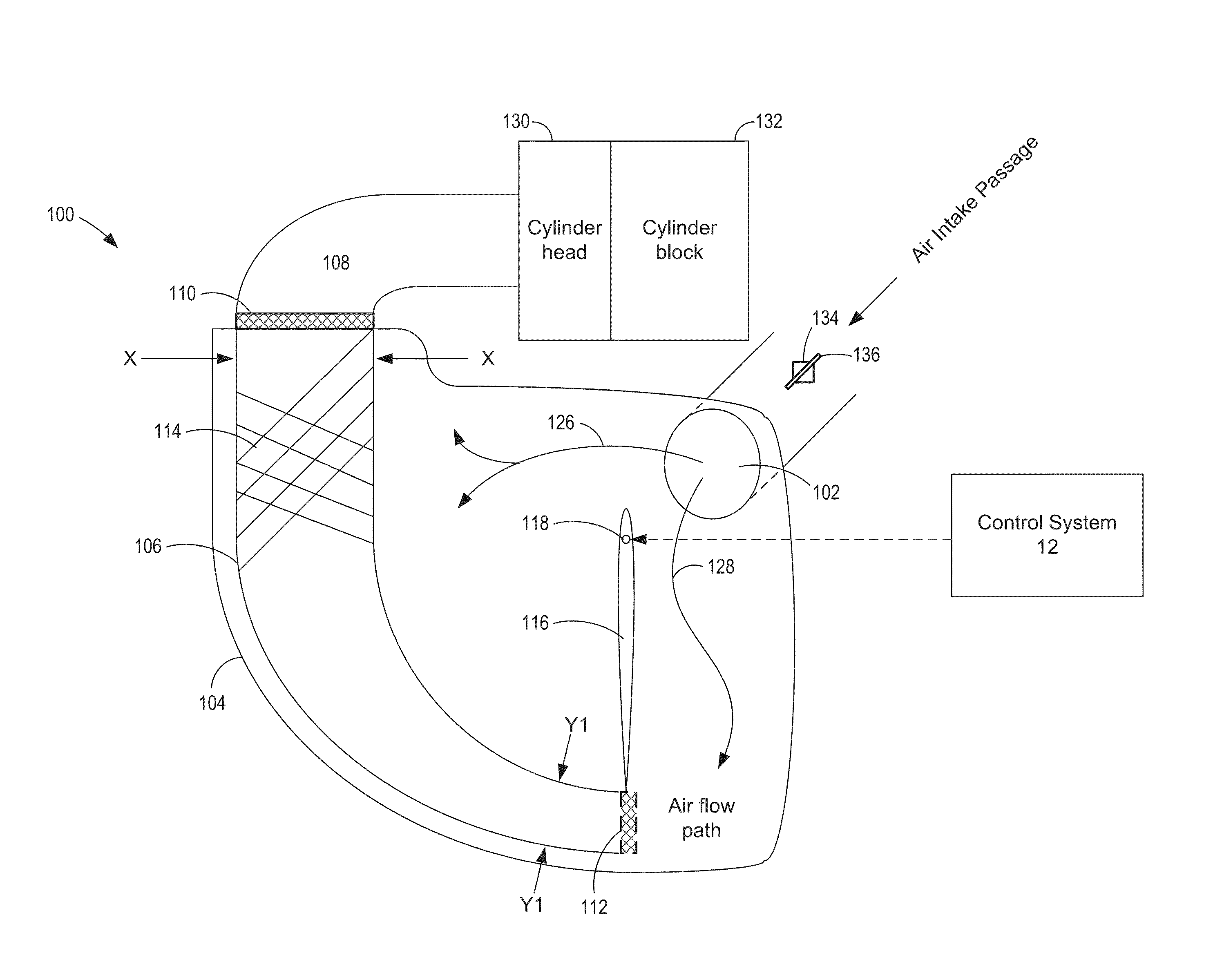
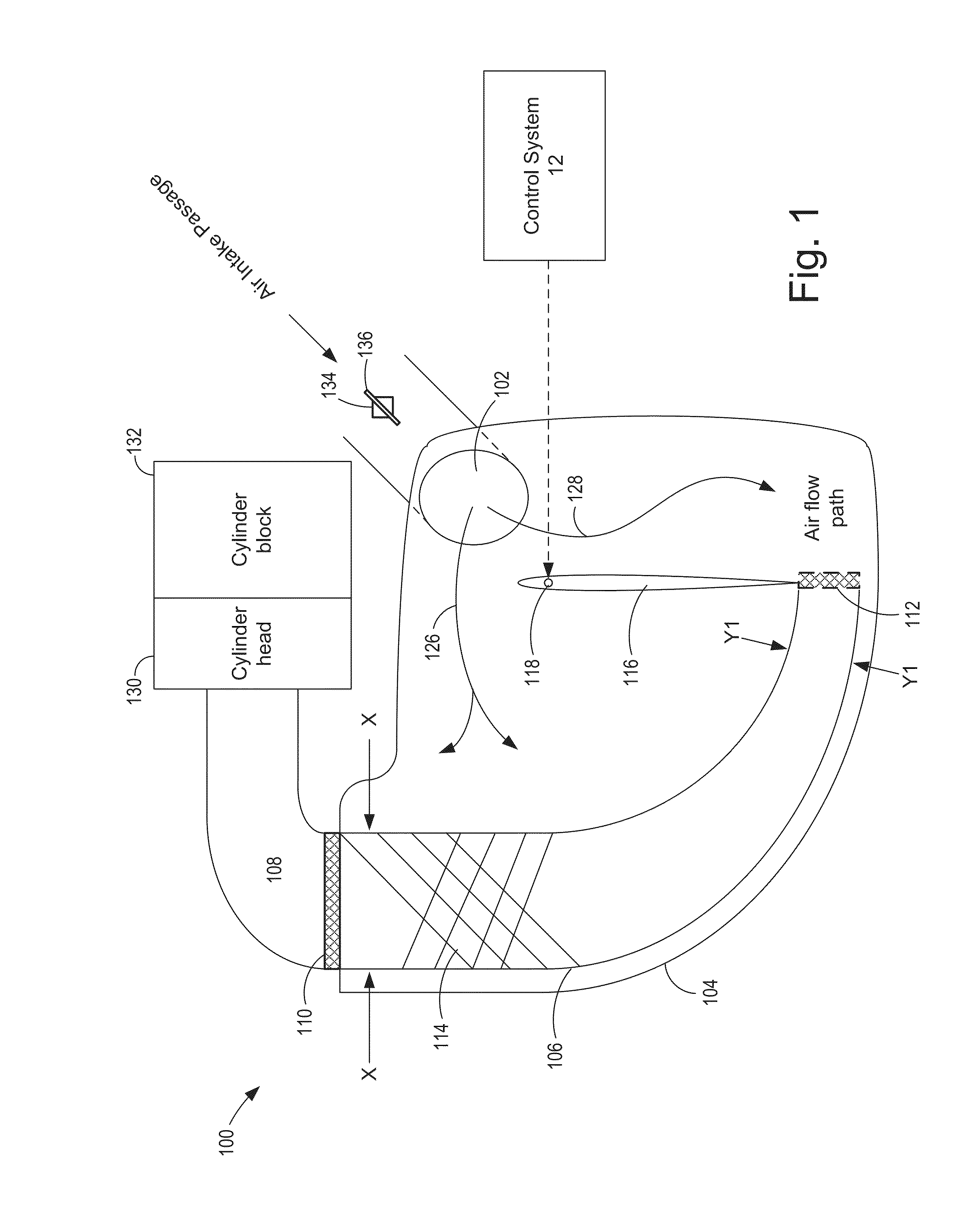
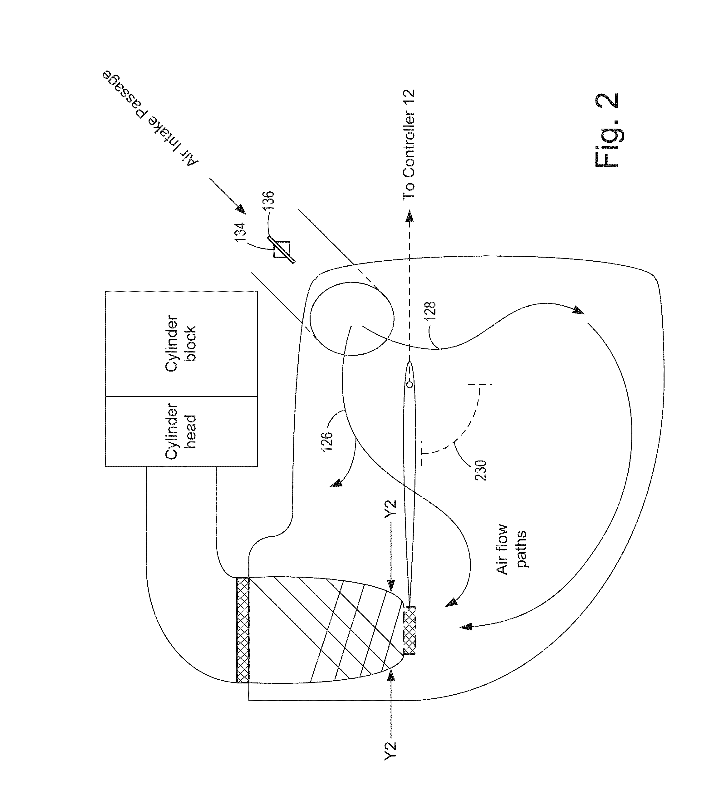
[0015]The present description relates to a system and method for controlling the flow of air to intake ports of an engine. The method involves adjusting the length of flexible intake manifold runners comprised of helically wound braids in a manner that also changes the cross-sectional area. In FIGS. 1 and 2, exemplary long and short curved runners are shown to illustrate how air flows through the plenum assembly of the engine in each configuration. Then, FIGS. 3 and 4 show side view schematic diagrams of an example I4 engine block with multiple braided runners in the long and short configurations, respectively, to illustrate how linkage arms connected to the braided runners operate as a unit when adjusting the length of the runners. Because runner length is continuously variable, the flow chart of FIG. 5 describes a method for adjusting the runner length based on the engine operating conditions in a manner that also changes the cross-sectional area, which allow for the flow of air d...


PUM


Abstract

A system and method for controlling the flow of air to an intake port of an engine is described that includes a flexible intake manifold runner comprised of helically wound braids. In one example, the length and cross-sectional area are mechanically interlinked. In this way, the flexible intake manifold runner can be tuned over a wider operating band while maintaining a lower cost design.

Description

FIELD[0001]The present description relates to a system and method for controlling a flow of air to intake ports of an engine.BACKGROUND AND SUMMARY[0002]Intake manifold runners include pipes designed to deliver a flow of air to combustion chambers within an engine. However, during certain parts of the engine drive cycle, intake valves are closed and prevent the air from flowing. When one or more intake valves open, a pressure wave develops within the runner and may increase the amount of air entering the open cylinder chamber. Therefore, under some operating conditions (e.g. at certain RPMs), the time when the propagating pressure wave encroaches upon the intake valve may align with intake valve opening, which causes a significant improvement in the volumetric efficiency and thereby the performance of the engine. For this reason, the airflow may depend on the geometry of a runner. For instance, the time for a pressure wave to propagate through a long manifold runner and back to an i...

Claims


Application Information

Patent Timeline
Patent Type & Authority Patents(United States)
IPC IPC(8): F02M35/10F02M35/104F02B27/02
CPCF02M35/104F02B27/0236F02M35/10072F02M35/10137F02M35/10301F02M35/10334Y02T10/146Y02T10/12
Inventor FABROS, CHARLES
Owner FORD GLOBAL TECH LLC
Why Eureka
Try Eureka