Device for centering and guiding the rotation of a turbomachine shaft

a technology of rotating shaft and rotating shaft, which is applied in the direction of machines/engines, bearing unit rigid supports, liquid fuel engines, etc., can solve the problems of increasing the axial bulkiness of the device, and possibly reducing the mechanical strength of the deformable portion of the support. , to achieve the effect of simple, effective and inexpensiv

Active Publication Date: 2016-03-08
SN DETUDE & DE CONSTR DE MOTEURS DAVIATION S N E C M A
View PDF13 Cites 8 Cited by
  • Summary
  • Abstract
  • Description
  • Claims
  • Application Information

AI Technical Summary

Benefits of technology

[0013]A particular object of the invention is to provide a simple, effective, and inexpensive solution to the problem of the bulkiness of prior art devices for centering and guidance.

Problems solved by technology

A device of this type is relatively bulky, in particular in an axial direction, thereby preventing it from being mounted in an engine of small size.
Any increase in the flexibility of a bearing support may in particular result in lengthening the deformable annular portion of the support, thereby nevertheless increasing the axial bulkiness of the device and possibly diminishing the mechanical strength of the deformable portion of the support.
Nevertheless, lengthening this space likewise gives rise to an increase in the axial bulkiness of the device.

Method used


Image

  • Device for centering and guiding the rotation of a turbomachine shaft
  • Device for centering and guiding the rotation of a turbomachine shaft
  • Device for centering and guiding the rotation of a turbomachine shaft

Examples


Embodiment Construction

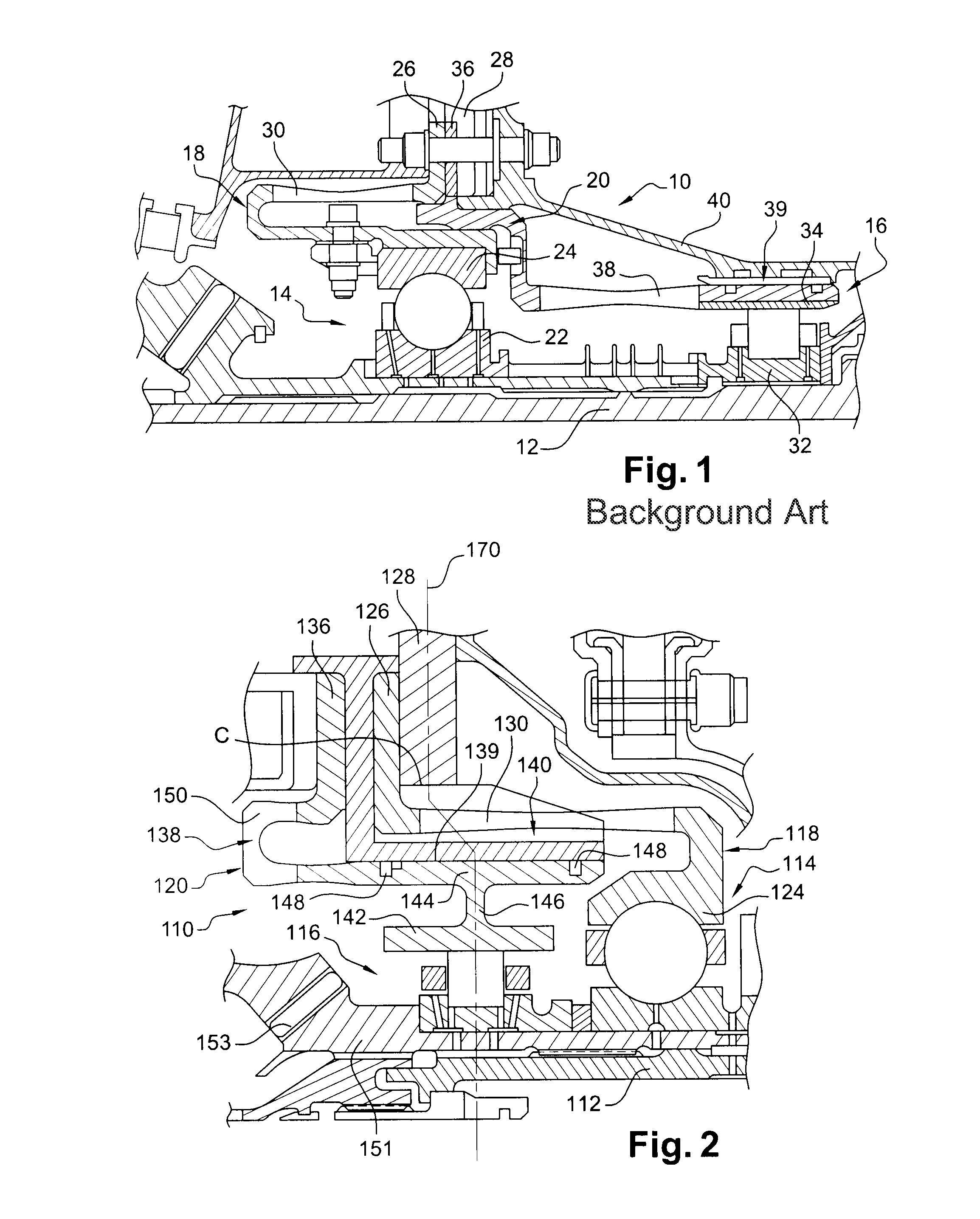
[0039]Reference is made to FIG. 1, which shows a prior art device 10 for centering and guiding rotation of a shaft 12 of a high pressure compressor of a turbine engine, the device comprising a ball bearing 14 and a roller bearing 16 mounted around the shaft 12 and carried respectively by two relatively flexible annular supports 18 and 20. In the art, the device 10 is referred to as a flexible-flexible “duplex” bearing.

[0040]The ball bearing 14 has a series of balls guided in a raceway defined by an inner ring 22 and an outer ring 24, the inner ring 22 being fastened on the shaft 12 and the outer ring 24 being fastened to one end of the annular support 18 that has, at its other end, an annular flange 26 for fastening to an annular flange 28 of an intermediate casing of the turbine engine. The support 18 has a section that is substantially C-shaped and it includes an elastically deformable annular portion 30 that confers a certain amount of flexibility to the support.

[0041]The roller ...


PUM


Abstract

A device for centering and guiding rotation of a turbine engine shaft. The device includes a roller bearing and a ball bearing mounted around the shaft and carried respectively by first and second flexible annular supports, together with an oil film compression damper having a rigid annular support arranged around the roller bearing, the supports of the ball bearing and of the damper, and the roller bearing being stacked transversely, extending one around another.

Description

BACKGROUND OF THE INVENTION[0001]1. Field of the Invention[0002]The present invention relates to a device for centering and guiding rotation of a shaft, in particular in a turbine engine.[0003]2. Description of the Related Art[0004]In general, a turbine engine shaft is centered and guided in rotation by two support means, respectively located upstream and downstream, one of the support means possibly comprising two rolling bearings mounted beside each other.[0005]In the art, when a bearing for guiding the shaft has only one rolling bearing, the guide bearing is commonly said to be a “simplex” bearing and is a roller or ball bearing, for example, that is carried by a rigid annular support extending around the shaft.[0006]When a guide bearing has two rolling bearings, the guide bearing is commonly said to be a “duplex” bearing and it generally comprises a roller bearing and a ball bearing.[0007]The ball bearing of the duplex bearing is carried by an annular support possessing a certai...

Claims


Application Information

Patent Timeline
Patent Type & Authority Patents(United States)
IPC IPC(8): F01D25/16F16C27/04F16C19/49F16C27/00F16C19/54
CPCF16C27/04F01D25/164F05D2230/64F16C19/49F16C19/545F16C27/00F16C2360/23F16C19/54F16C27/045
Inventor ROUESNE, IVAN, GUY
Owner SN DETUDE & DE CONSTR DE MOTEURS DAVIATION S N E C M A
Why Eureka
Try Eureka