Systems and methods for stand-off inspection of aircraft structures

a technology for aircraft structures and standoff inspection, which is applied in the direction of optically investigating flaws/contamination, structural/machine measurement, instruments, etc., can solve the problems of difficult to obtain accurate measurements of aircraft locations defined in aircraft coordinates, difficult to measure a precise position in the desired coordinate system, and laborious task of finding and accurately measuring the locations of potential damage on a structure,

Active Publication Date: 2016-03-15
THE BOEING CO
View PDF9 Cites 31 Cited by
  • Summary
  • Abstract
  • Description
  • Claims
  • Application Information

AI Technical Summary

Problems solved by technology

Finding and accurately measuring the locations of potential damage on a structure, such as a large commercial airplane, can be a laborious task.
From two-dimensional images alone, it is difficult to get accurate measurements of aircraft locations defined in aircraft coordinates.
But even with a reference scale, it can be difficult to measure a precise position in the desired coordinate system.
Determining the correct location is especially difficult in areas where few uniquely identifiable landmark features exist.
In addition, human analysis of a large number of potential damage areas would likely be error prone.
One specific problem in automated inspection is to provide a system and a method for automated inspection of dielectric tops on an aircraft wing.
It is known that dielectric tops are susceptible to cracking after a certain number of years in service.
Cracks above a certain length may require repair or replacement of the dielectric tops.

Method used


Image

  • Systems and methods for stand-off inspection of aircraft structures
  • Systems and methods for stand-off inspection of aircraft structures
  • Systems and methods for stand-off inspection of aircraft structures

Examples


Embodiment Construction

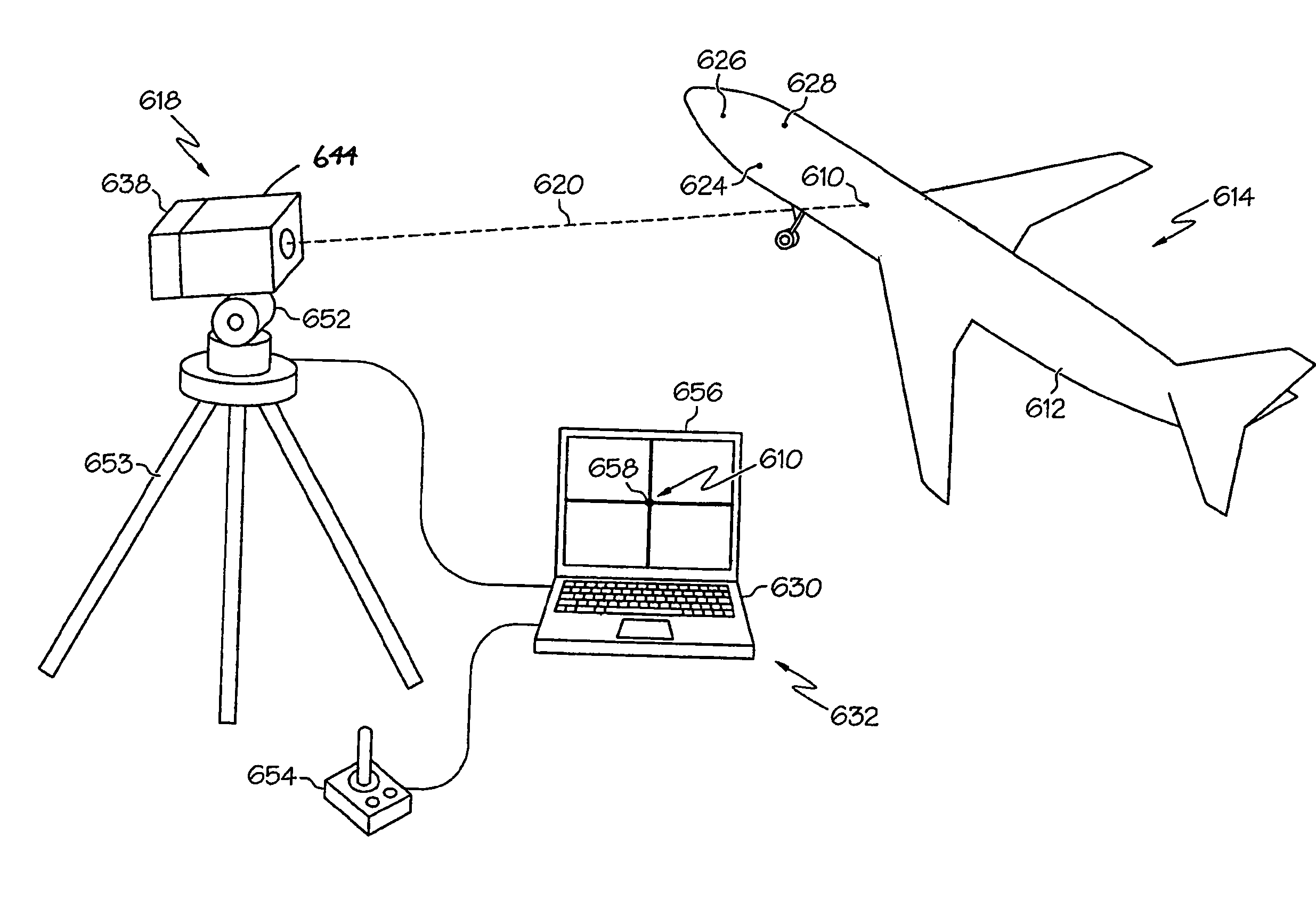
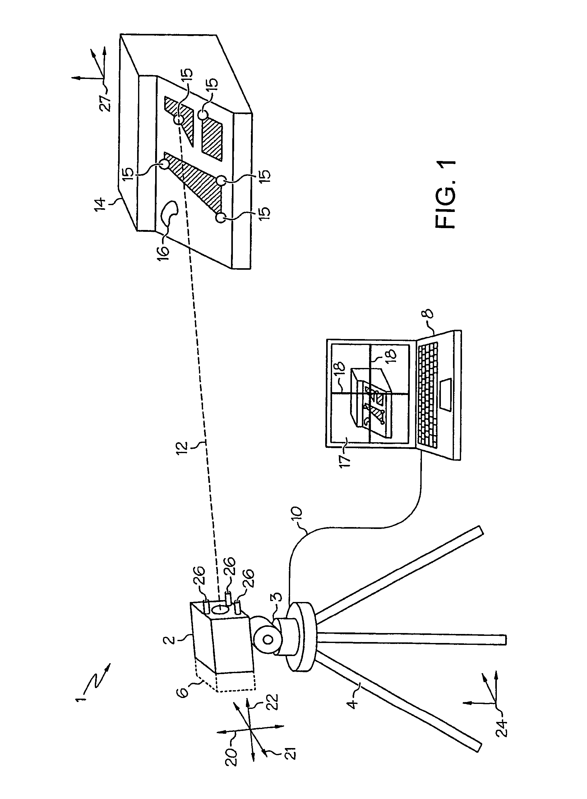
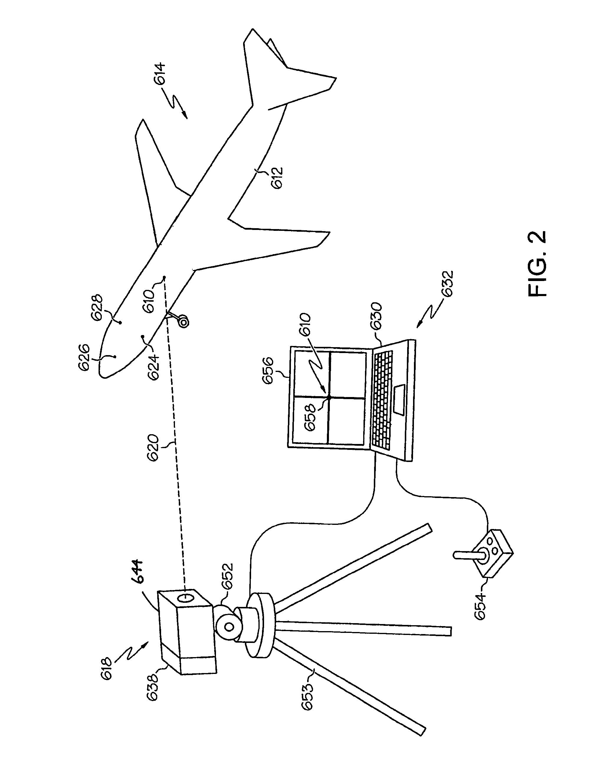
[0030]FIG. 1 depicts one embodiment of a local positioning system 1 suitable for providing position data on a target object defined in the local coordinate system of the target object. The local positioning system 1 may comprise a video camera 2 having automated (remotely controlled) zoom capabilities. The video camera 2 may additionally include an integral crosshair generator to facilitate precise locating of a point within an optical image field display 17 for displaying video camera output on a personal computer or other display device 8. In applications in which the crosshair generator is not an integral component of the video camera 2, a crosshair generator 6 (shown in phantom) may be connected to the video camera 2 as a separate element for this purpose or overlaid on the video stream on the personal computer or display device 8.

[0031]The video camera 2 may be coupled to a motion-controlled pan-tilt mechanism 3 mounted on a tripod support 4 or an alternative support frame (e.g...


PUM

PropertyMeasurementUnit
wavelengthaaaaaaaaaa
lengthaaaaaaaaaa
distanceaaaaaaaaaa

Abstract

A system for stand-off inspection comprising local positioning system hardware and a nondestructive evaluation instrument supported by a pan-tilt mechanism. The system further comprises a computer system that is programmed to perform the following operations: (a) directing the local positioning system hardware toward an area of a surface on a target object by control of the pan-tilt mechanism; (b) activating the local positioning system hardware to acquire an image; (c) processing the image to determine whether an anomaly is present in the area; (d) if an anomaly is present, determining coordinates of a position of the anomaly in a coordinate system of the target object; and (e) directing the nondestructive evaluation instrument toward a position corresponding to the coordinates. Optionally, the computer system is further programmed to measure one or more characteristics of the anomaly.

Description

BACKGROUND[0001]This disclosure generally relates to automated systems and methods for stand-off inspection of structures, such as aircraft components. In particular, this disclosure relates to automated methods and systems for locating visible differences on a structural component from a distance and accurately measuring the locations of potential damage relative to a coordinate system of the inspected structure.[0002]Finding and accurately measuring the locations of potential damage on a structure, such as a large commercial airplane, can be a laborious task. An efficient and automated process for addressing this problem would be valuable to many organizations involved in building and maintaining large vehicles and structures.[0003]From two-dimensional images alone, it is difficult to get accurate measurements of aircraft locations defined in aircraft coordinates. Often, an item of known dimensions (like a tape measure) is inserted in the picture to give the analyst a size referen...

Claims


Application Information

Patent Timeline
Patent Type & Authority Patents(United States)
IPC IPC(8): G01M99/00G01N21/88G01N21/84
CPCG01M99/00G01N21/8422G01N21/8851G01N2021/8867
Inventor GEORGESON, GARY E.TROY, JAMES J.LEA, SCOTT W.
Owner THE BOEING CO
Why Eureka
Try Eureka