Opaque bridge for peripheral component interconnect express bus systems

a peripheral component and express bus technology, applied in the field of bus interfaces, can solve problems such as compatibility problems, and it is not possible to construct a desired system using a pcie bus, and achieve the effect of facilitating the introduction of a discontinuity in the bus number

Active Publication Date: 2016-03-15
NATIONAL INSTRUMENTS
View PDF10 Cites 7 Cited by
  • Summary
  • Abstract
  • Description
  • Claims
  • Application Information

AI Technical Summary

Benefits of technology

[0012]A special piece of hardware may facilitate the introduction of a discontinuity in the bus numbers. Since, under normal conditions, the discontinuity prevents the system from operating properly by virtue of breaking the routing mechanism, the HW may be operated in a manner that ensures that the system functions properly, even as the discontinuity is introduced. A system and method may also be implemented to translate the BDFs (bus device functions) during operation, in a manner that ensures that the bus configuration also remains fully functional, and the host remains unaware of any changes that may have been made in the physical subsystem. In one set of embodiments, a mechanism may be established to route PCIe packets based on packet type in addition to routing the packets according to address information that may be included in the packet. By routing the packets based on packet type, it becomes possible to couple a host to a PCIe subsystem requiring more bus numbers than provided for in a standard PCIe switch fabric configuration.

Problems solved by technology

There are conditions under which it may not be possible to construct a desired system using a PCIe bus (i.e. PCIe switch fabric), as there may not be enough bus numbers available.
There are typically eight (8) bits available for setting bus numbers in a PCIe switch fabric, which may lead to compatibility problems.

Method used


Image

  • Opaque bridge for peripheral component interconnect express bus systems
  • Opaque bridge for peripheral component interconnect express bus systems
  • Opaque bridge for peripheral component interconnect express bus systems

Examples


Embodiment Construction

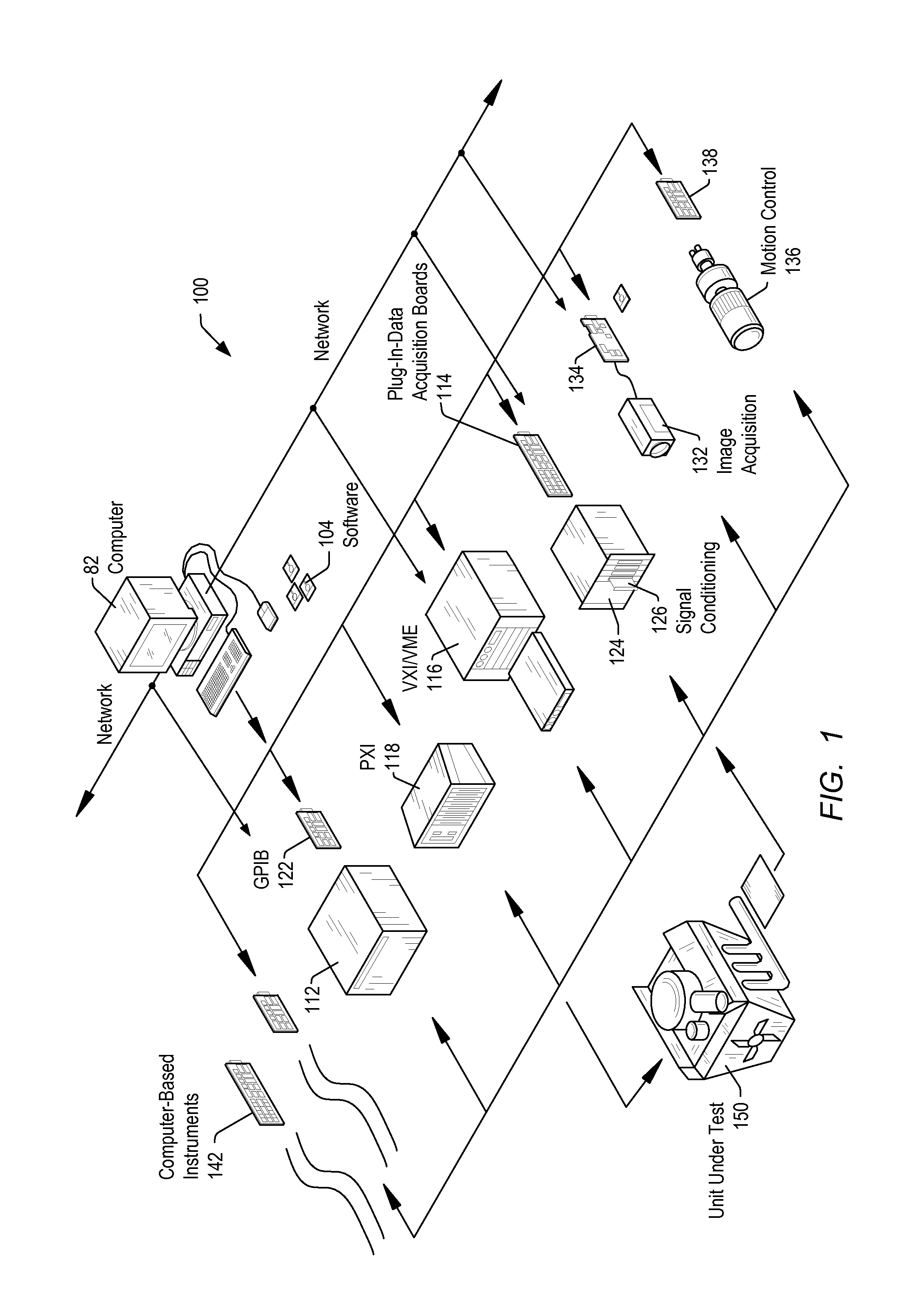
[0028]FIG. 1 illustrates an exemplary instrumentation control system 100 which may be configured according to embodiments of the present invention. System 100 comprises a host computer 82 which may couple to one or more instruments configured to perform a variety of functions using timing control implemented according to various embodiments of the present invention. Host computer 82 may comprise a CPU (Central Processing Unit), a display screen, memory, and one or more input devices such as a mouse or keyboard as shown. Computer 82 may operate with one or more instruments to analyze, measure, or control a unit under test (UUT) or process 150. The one or more instruments may include a GPIB (General Purpose Interface Bus) instrument 112 and associated GPIB interface card 122, a data acquisition board 114 inserted into or otherwise coupled with chassis 124 with associated signal conditioning circuitry 126, a VXI (VERSAmodule Eurocard [VME] eXtensions for Instrumentation) instrument 116...


PUM


Abstract

A host system may couple to a PCIe subsystem. During setup of the PCIe subsystem, the BIOS in the host system may first be informed that the devices to be coupled are not PCIe devices, and certain amount of memory is required for these devices. The BIOS may therefore not attempt to configure the devices, and may instead allocate the required memory space. When the operating system boots up, it may not attempt to configure the devices, loading a custom driver instead of an existing PCI driver to configure the bus. Once loaded, the custom driver may configure the devices, then inform the OS that there are PCIe devices in the system at the specified addresses, which may cause the OS to load and execute existing PCIe device drivers to operate / use the devices. The proprietary driver may also be used to handle traffic between the PCIe drivers and the OS.

Description

BACKGROUND OF THE INVENTION[0001]1. Field of the Invention[0002]This invention relates generally to bus interfaces, and, more particularly, to the design of an improved Peripheral Component Interconnect Express Bus interface.[0003]2. Description of the Related Art[0004]PCI Express (Peripheral Component Interconnect Express, also abbreviated as PCIe), is a high-speed serial computer expansion bus standard offering numerous improvements over the older PCI, PCI-X, and AGP (Accelerated Graphics Port) bus standards. These improvements include higher maximum system bus throughput, lower I / O pin count and a smaller physical footprint, better performance-scaling for bus devices, more detailed error detection and reporting mechanism, and native hot-plug functionality. Conceptually, the PCIe bus is a high-speed serial interconnect bus using shared address / data lines. Accordingly, the PCIe bus differs from the older PCI bus in its bus topology. While PCI uses a shared parallel bus architecture...

Claims


Application Information

Patent Timeline
Patent Type & Authority Patents(United States)
IPC IPC(8): G06F9/24G06F15/177G06F9/44G06F13/40G06F12/02G06F13/38G06F13/36G06F13/00
CPCG06F13/4045G06F9/4401G06F12/0246G06F13/00G06F13/36G06F13/385G06F13/4027G06F13/4081G06F2213/0026G06F13/16G06F13/4022G06F13/4068G06F13/4282
Inventor GARDINER, ERIC R.HEARN, JONATHAN W.JONES, CRAIG S.TONGEN, JASON D.
Owner NATIONAL INSTRUMENTS
Why Eureka
Try Eureka