Methods and systems for transforming luminal images

a luminal image and luminal technology, applied in image enhancement, instruments, applications, etc., can solve the problems of improper display of vessel features, distortion of images, misalignment, etc., and achieve the effect of greater consistency among frames

Active Publication Date: 2016-03-22
VOLCANO CORP
View PDF1078 Cites 21 Cited by
  • Summary
  • Abstract
  • Description
  • Claims
  • Application Information

AI Technical Summary

Benefits of technology

[0011]In one example, compensating for frame alignment distortion includes identifying a reference position in each image frame and aligning each frame using the reference position. Another example of compensating for frame alignment includes aligning the reference position in all frames and calculating a new reference position from the aligned frames. A specific reference position can be the center of the lumen, but any reference position in the image frame can be used. Steps for aligning to the center of a lumen may include fitting a geometric shape to a lumen border, calculating a reference position within the area circumscribed by the geometric shape and aligning the image center to the reference position. The geometric shape to be fit to the lumen border includes, but is not limited to, a centroid, a circle or an ellipse. For greater consistency among frames for alignment purposes, the reference position can be smoothed across all image frames.

Problems solved by technology

Although rotational imaging systems have the potential for providing detailed images of the inside of vessels, the displayed image often includes various distortions arising during movement of the device through the lumen.
For example, distortions can include images in a series appearing to be misaligned, improper display of vessel features due to the imaging device not precisely following the contours of the vessel, or distortion arising from the helical motion of the device as it is moved through the vessel.
These distortions result in considerable intra- and inter-observer variability that may lead to conflicting or incorrect patient diagnosis.

Method used


Image

  • Methods and systems for transforming luminal images
  • Methods and systems for transforming luminal images
  • Methods and systems for transforming luminal images

Examples


Embodiment Construction

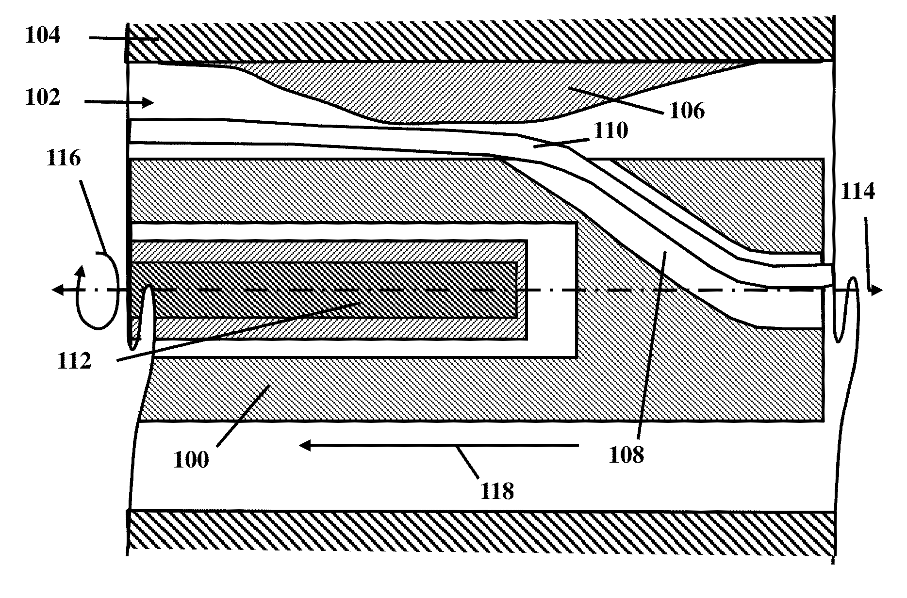
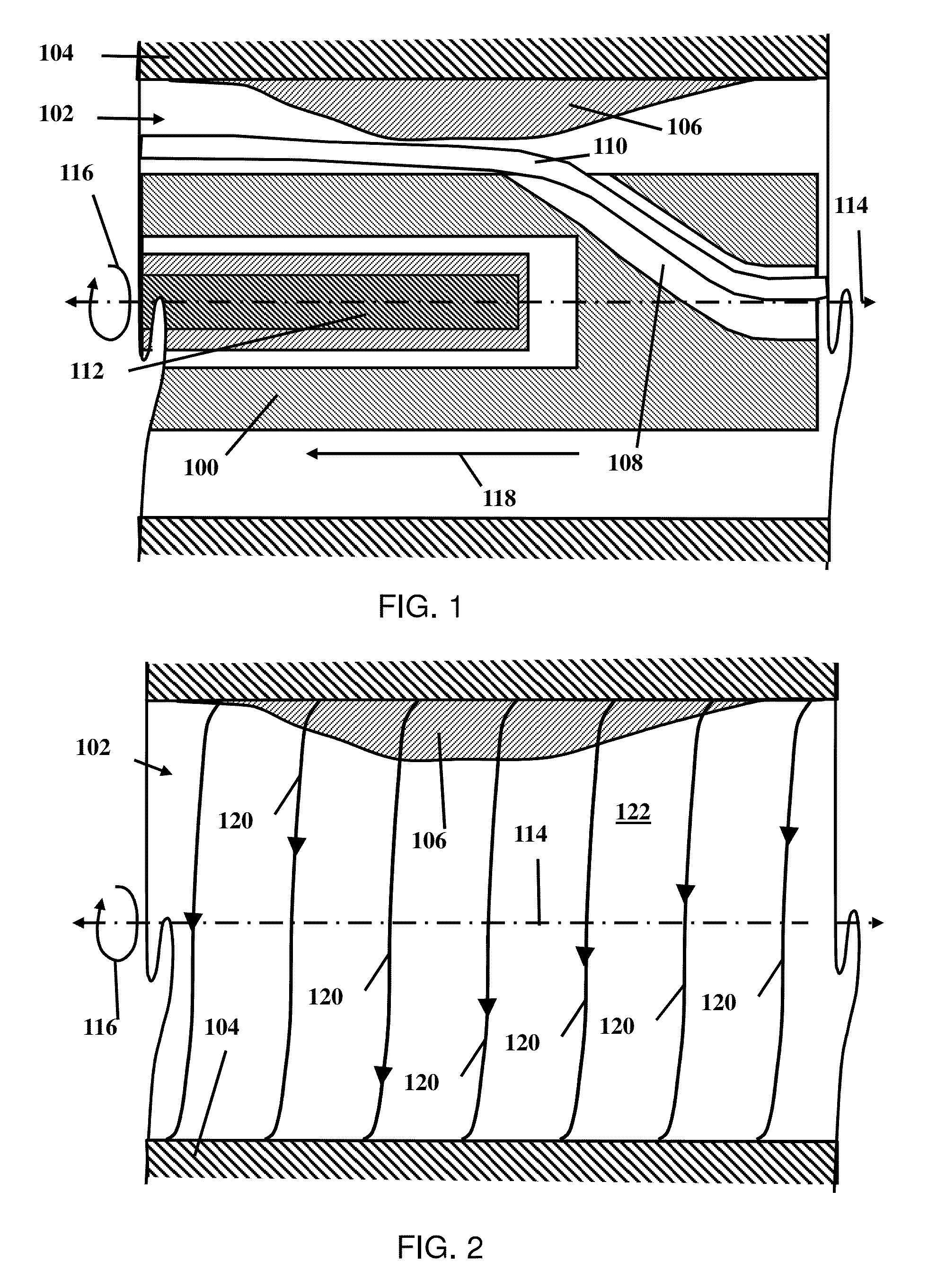
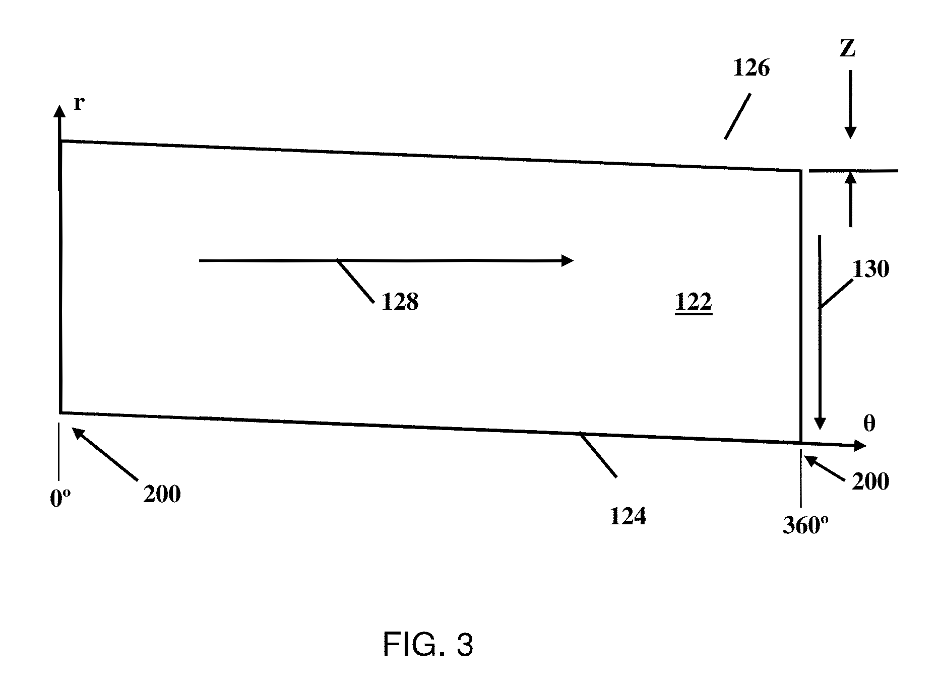
[0030]The invention provides methods and systems for correcting translational distortion in a medical image of a lumen of a biological structure. The method facilitates vessel visualization in intravascular images (e.g. IVUS, OCT) used to evaluate the cardiovascular health of a patient. Using the methods and systems described herein it is simpler for a provider to evaluate vascular imaging data, which is typically distorted due to cardiac vessel-catheter motion while the image was acquired. The invention applies a motion correction algorithm to the images prior to generating vessel-centric images as an alternative to traditional catheter-centric display views.

[0031]Medical imaging is a general technology class in which sectional and multidimensional anatomic images are constructed from acquired data. The data can be collected from a variety of acquisition systems including, but not limited to, magnetic resonance imaging (MRI), radiography methods including fluoroscopy, x-ray tomogra...


PUM


Abstract

The invention provides methods and systems for correcting translational distortion in a medical image of a lumen of a biological structure. The method facilitates vessel visualization in intravascular images (e.g. IVUS, OCT) used to evaluate the cardiovascular health of a patient. Using the methods and systems described herein it is simpler for a provider to evaluate vascular imaging data, which is typically distorted due to cardiac vessel-catheter motion while the image was acquired.

Description

RELATED APPLICATIONS[0001]This application is a continuation-in-part of U.S. patent application Ser. No. 14 / 044,990, filed Oct. 3, 2013, which claims priority to U.S. Provisional Application No. 61 / 710,410, filed Oct. 5, 2012. This application additionally claims priority to U.S. Provisional Application No. 61 / 781,660, filed Mar. 14, 2013. The contents of all of the noted applications are incorporated by reference herein in their entireties.FIELD OF THE INVENTION[0002]The invention relates to methods and systems for correcting consecutive images of a lumen to compensate for motion of the lumen, motion of the imaging device, or variation of the placement of the imaging device with respect to the center of the lumen.BACKGROUND[0003]Medical imaging is commonly used to evaluate various biological structures of a patient. A common type of imaging system is a rotational medical imaging system (e.g., optical coherence tomography (OCT) or intravascular ultrasound (IVUS)). Those types of sys...

Claims


Application Information

Patent Timeline
Patent Type & Authority Patents(United States)
IPC IPC(8): G06K9/00G06T7/00A61B6/00
CPCG06T7/0012G06T7/0028G06T2207/10068G06T2207/10101G06T2207/10136G06T2207/30101G06T7/33G06T5/002G06T7/0014G06T7/337G06T7/38G06T2207/10132
Inventor ZAGRODSKY, VLADIMIRSTURM, BERNHARDBEGIN, ELIZABETHSPROUL, JASON
Owner VOLCANO CORP
Why Eureka
Try Eureka