
Hybrid radiant energy aircraft engine

a technology of radiant energy and aircraft engines, applied in hybrid vehicles, machines/engines, transportation and packaging, etc., can solve the problems of very short flight range of aircraft, high maintenance cost of reciprocating engines, and high cost of turbine engines

Active Publication Date: 2016-03-29
SEPARATION DESIGN GROUP
View PDF40 Cites 10 Cited by
  • Summary
  • Abstract
  • Description
  • Claims
  • Application Information

AI Technical Summary

Problems solved by technology

Reciprocating engines require very high maintenance and turbine engines are very expensive to manufacture because of the exotic materials used in the hot section of the engine.
These aircraft, however, have very short flight range because the energy density of lithium ion batteries is only about 190 watt hours per kilogram.
So it is obvious that even with advances in battery energy density, electrically operated aircraft will have limited distance capabilities.

Method used


Image

  • Hybrid radiant energy aircraft engine
  • Hybrid radiant energy aircraft engine
  • Hybrid radiant energy aircraft engine

Examples


Embodiment Construction

Definitions

[0030]The following definitions are provided for the full understanding of terms used in this specification.

[0031]As used herein, the article “a” means “at least one,” unless the context in which the article is used clearly indicates otherwise.

[0032]As used herein, “thermophotovoltaic cell” means any material capable of converting radiant energy into electricity. These cells are sometimes referred to as photovoltaic cells or concentrator photovoltaic cells.

[0033]As used herein, “thermoelectric cell” means any material capable of converting a temperature differential directly into electricity.

[0034]As used herein, “duct” means a housing having a basically cylindrical shape, having a hollow center section, having mounting tabs for internal components, and having contours that promote the acceleration of the fan and heated air, and having structural components that allow attachment to the aircraft and transmission of thrust forces.

[0035]As used herein, “cold mirrors” means a...


PUM


Abstract

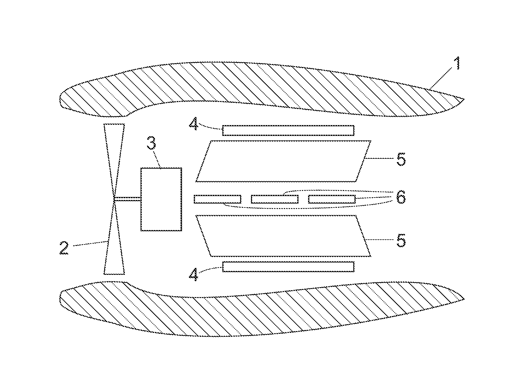
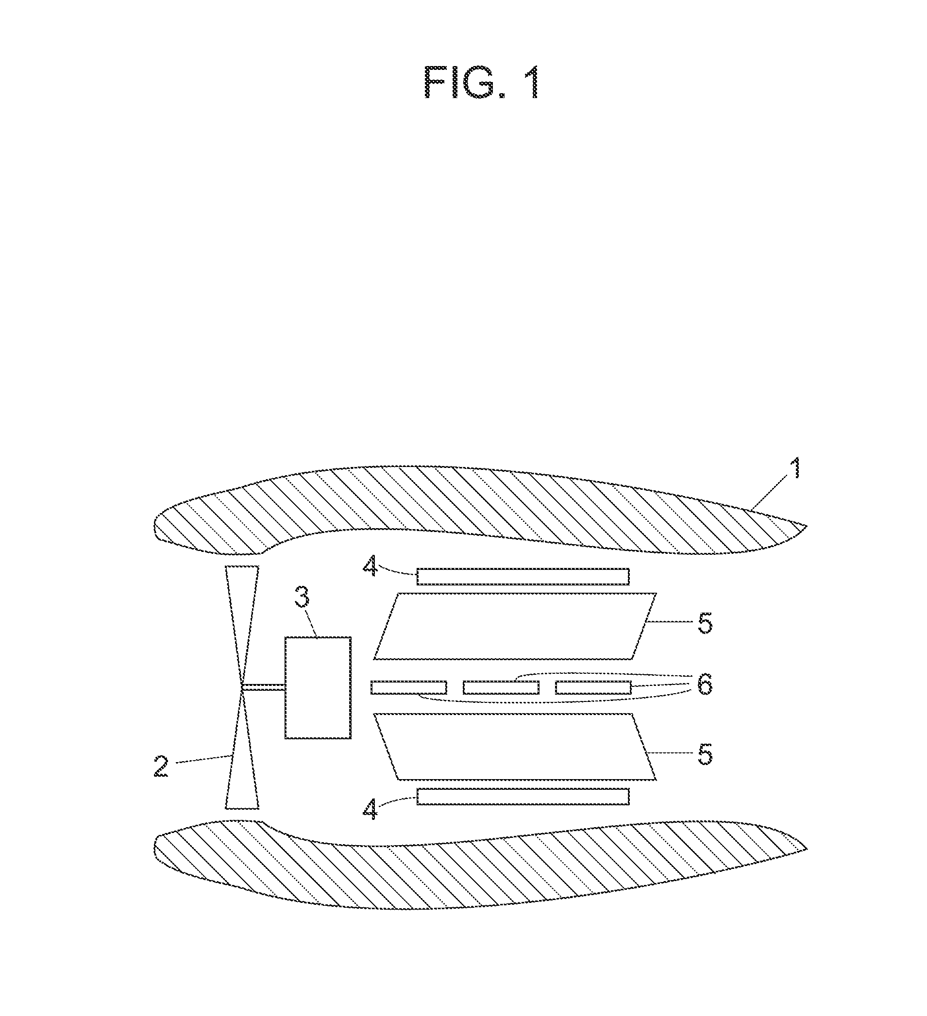
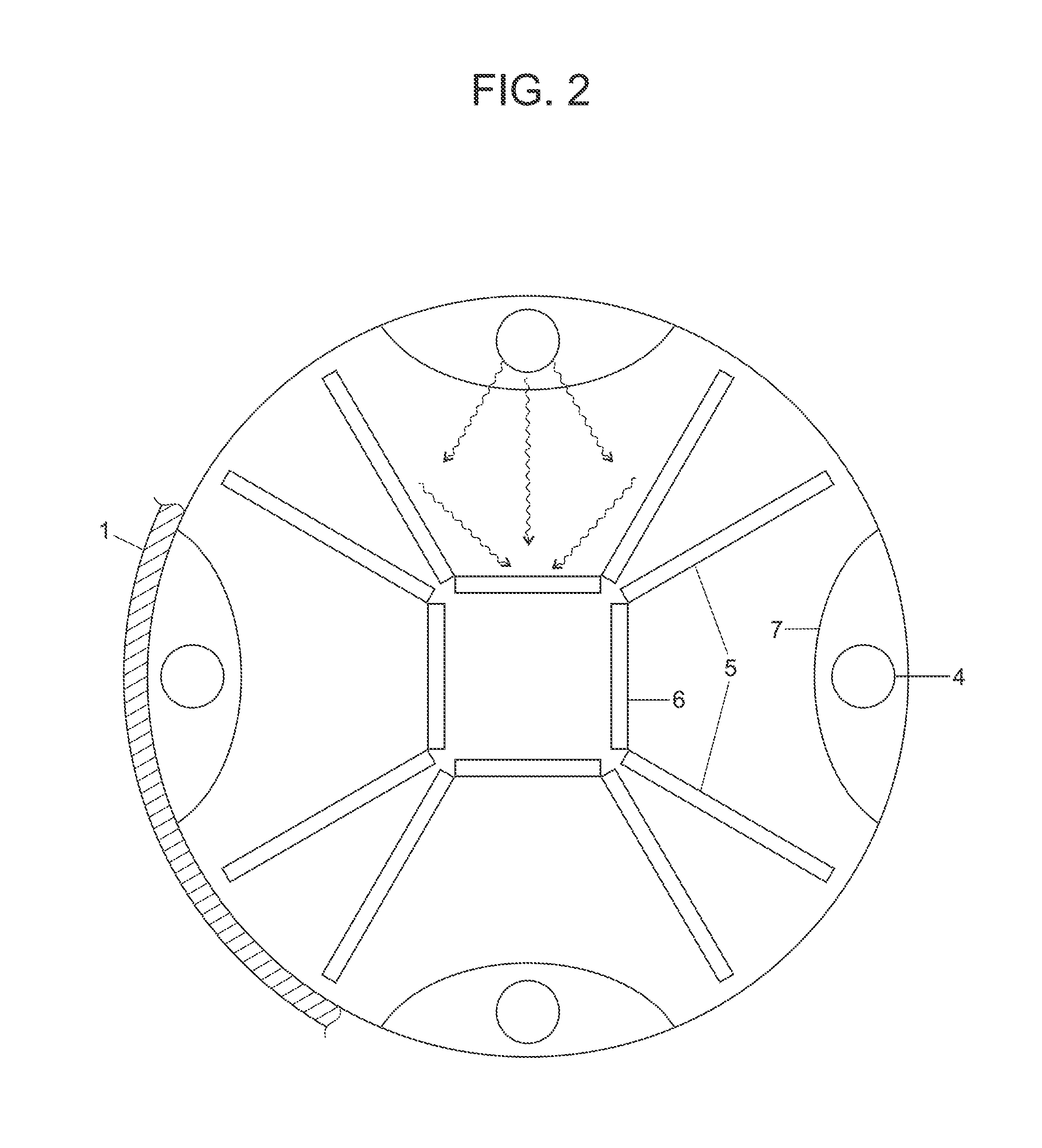
Hybrid aircraft propulsion systems are disclosed comprising an electrically driven ducted fan, a peripheral duct or enclosure, a combustion-produced source of radiant energy, radiant energy receivers or cold mirrors, and thermophotovoltaic or thermoelectric cell energy converters. An electric motor drives a partially or completely duct enclosed fan. Downstream and within the duct enclosure, radiant energy emitters irradiated receiver fins and thermophotovoltaic cells or thermoelectric cells. The receiver fins heat and expand the fan air, and the thermophotovoltaic cells or thermoelectric cells convert the radiant energy into electrical energy which is available to charge batteries and energize the fan motor. Thrust is provided via the acceleration of air by the fan and by the acceleration of air due to heat driven expansion.

Description

CROSS-REFERENCE TO RELATED APPLICATIONS[0001]This application claims the benefit of U.S. Provisional Application No. 61 / 643,479, filed May 7, 2012, the entirety of which is incorporated herein by reference.FIELD OF THE INVENTION[0002]The invention relates to aircraft engines capable of being operated by electricity and by the combustion of a liquid, gaseous, or solid fuel.BACKGROUND OF THE INVENTION[0003]Conventional aircraft engines utilize reciprocating engines, turbine driven propeller engines, or turbine engines which deliver thrust as a result of a combination of fan action and jet thrust. Reciprocating engines require very high maintenance and turbine engines are very expensive to manufacture because of the exotic materials used in the hot section of the engine. Reciprocating and turbine engines rely entirely on the combustion of a chemical fuel for their operation.[0004]Recently, because of advances in electric motor technology and battery energy density, short range small ai...

Claims


Application Information

Patent Timeline
Patent Type & Authority Patents(United States)
IPC IPC(8): F02K7/10F02K3/06B60K6/28B60K6/24F02C1/00F02K3/062
CPCB60K6/24B60K6/28F02C1/00F02K3/06F02K3/062Y02T10/6295Y02T10/62
Inventor GALBRAITH, STEPHEN, DOUGLAS
Owner SEPARATION DESIGN GROUP
Learn More