Valve drive assembly and valve using the same

a technology of valve drive assembly and valve drive, which is applied in the direction of valve details, plug valves, engine components, etc., can solve the problems of cost-intensive, narrow interference fit between both actuators having to be designed twice, and the solution is therefore quite expensive and cost-intensive to manufacture. , to achieve the effect of simple devices, faster production and reduced volume flow rate q

Active Publication Date: 2016-03-29
JOHNSON ELECTRIC SA
View PDF13 Cites 1 Cited by
  • Summary
  • Abstract
  • Description
  • Claims
  • Application Information

AI Technical Summary

Benefits of technology

[0009]The task of the invention is to improve an actuator for a valve drive assembly to regulate a flow of fluid, so that both the manufacture of the accessory parts and the fitting of the valve with the actuator is designed more cheaply, where the greater tolerances in manufacture shall be enabled and particularly the actuation unit of the valve is simplified. The required flow restriction can overall be implemented more stably, securely and precisely.
[0011]A valve unit is to regulate a flow of fluid from a modulation valve, where the valve chamber of the actuator is sealed by means of diaphragms disposed on valve body 2 and the valve is operated with operating rod 3. Flange 4 is erected on valve body 2, and formed of a lead-through for an operating rod 3. An actuator 1 is fastened to flange 4 as an operating element by means of a flange-type actuator base 13 and drives operating rod 3. Between flange 4 and operating rod 3 a further annular element, (also known as additional component part or additional material) is arranged, in accordance with the invention. Annular element can be an additional bushing 8 and / or another sleeve 9 or the flange 4 with an additional flange collar 10, or a separate sealing compound 11, or a particular welding material 16 that are arranged between the flange 4 and the operating rod 3. In this case, the effective length L of the annular gap 12 between the operating rod 3 and the annular element exceeds the material thickness H of the flange 4. Surprisingly, it has been found that if the length L of the annular gap 12 exceeds the thickness of the flange 4, the volume flow rate Q is further reduced. In another word, over this length L the volume flow rate Q can be precisely restricted and adjusted through the following mathematical relationship. That means a small change in the gap dimension h actually is able to have a great effect on the volume flow rate Q. The volume flow rate Q through the annular gap 12 is also highly dependent on the length L of the gap Q˜1 / L, as well as the gap dimension of the annular gap h with the relationship Q˜h3. By dimensioning the individual parts accordingly, the narrow lead-through provided with an interference fit between flange 4 and the operating rod 3 in prior art can then be replaced by using a annular element. As well as making savings in the manufacture of a necessary, highly-precise lead-through of the operating rod 3 comprises the interference fits, this also has considerable advantages in fitting the component parts. In other words, the production can be done faster than before with simpler devices. Because the component parts can be provided with larger interference fits, the relevant component parts to be fitted to each other, i.e., the flange 4, the annular element and the operating rod 3 can be produced using manufacturing processes that are simpler and considerably cheaper with larger dimensional tolerances, such as deep-drawing or stamping, for example, in the mass production presented here.
[0012]In the novel actuator 1 for a valve unit to regulate a flow of fluid from a modulation valve, which is sealed by means of diaphragms up to the valve body 2 and is operated with this actuator 1, an operating rod 3 reaching as far as into the valve body 2 is arranged. This operating rod 3 is, as is known, guided by the flange 4 and the lead-through realizes a defined maximum flow of the fluid. In the lead-through of the operating rod 3 through flange 4, in a novel way essentially the effective length L of the annular gap 12 between the operating rod 3 and annular element exceeds the material thickness H of the flange 4 defined as broadly as possible. The advantage of this design comprises the fact that now, by means of a simpler mathematical calculation through the dimensioning of the component parts, the maximum permitted volume flow rate Q of a fluid from the inside of a defective valve body (with torn diaphragm) can be restricted and set in advance precisely in the actuator chamber 6. The tolerances can be controlled without difficulty with mass production technologies, by which the arrangement can be achieved cheaply.
[0013]It is of a considerable advantage if the annular element is structurally integrated into actuator 1, for example, is formed with a flanged collar 10 directly moulded on.
[0014]In general, it is also possible that the effective annular gap 12 in the actuator 1 for a valve unit is formed between the annular element and the flange 4. This leads to a better and simpler fitting of the component parts to each other. However, the flange 4 is then, for example, to be provided with a flange collar 10 or an additional bushing 8, or the flange is to be designed generally much thicker than before in this area, in order to be able to achieve the required annular gap length.

Problems solved by technology

However, in the event of a fault, for example, if a sealing diaphragm is damaged (tear in the diaphragm), this intermediate chamber facing the valve fills with the fluid and the operating pressure of the fluid retained in said chamber.
Such interference fits are cost-intensive, as they have the condition of a high expense both in the mechanical production of the component parts and in the assembly of the operating rod and the flange.
Nevertheless, this raises the problem that at the lead-through points of the operating rods, the narrow interference fit between both of the actuators must be designed twice.
This solution is therefore quite expensive and cost-intensive to manufacture.

Method used


Image

  • Valve drive assembly and valve using the same
  • Valve drive assembly and valve using the same
  • Valve drive assembly and valve using the same

Examples


Embodiment Construction

[0021]Various embodiments of the present invention are described, by way of example only, with reference to the drawings, in which identical or related structures, elements, or parts may be labeled with the same reference numerals throughout the figures. Dimensions of components and features shown in the figures are generally chosen for convenience and clarity of presentation and are not necessarily to scale.

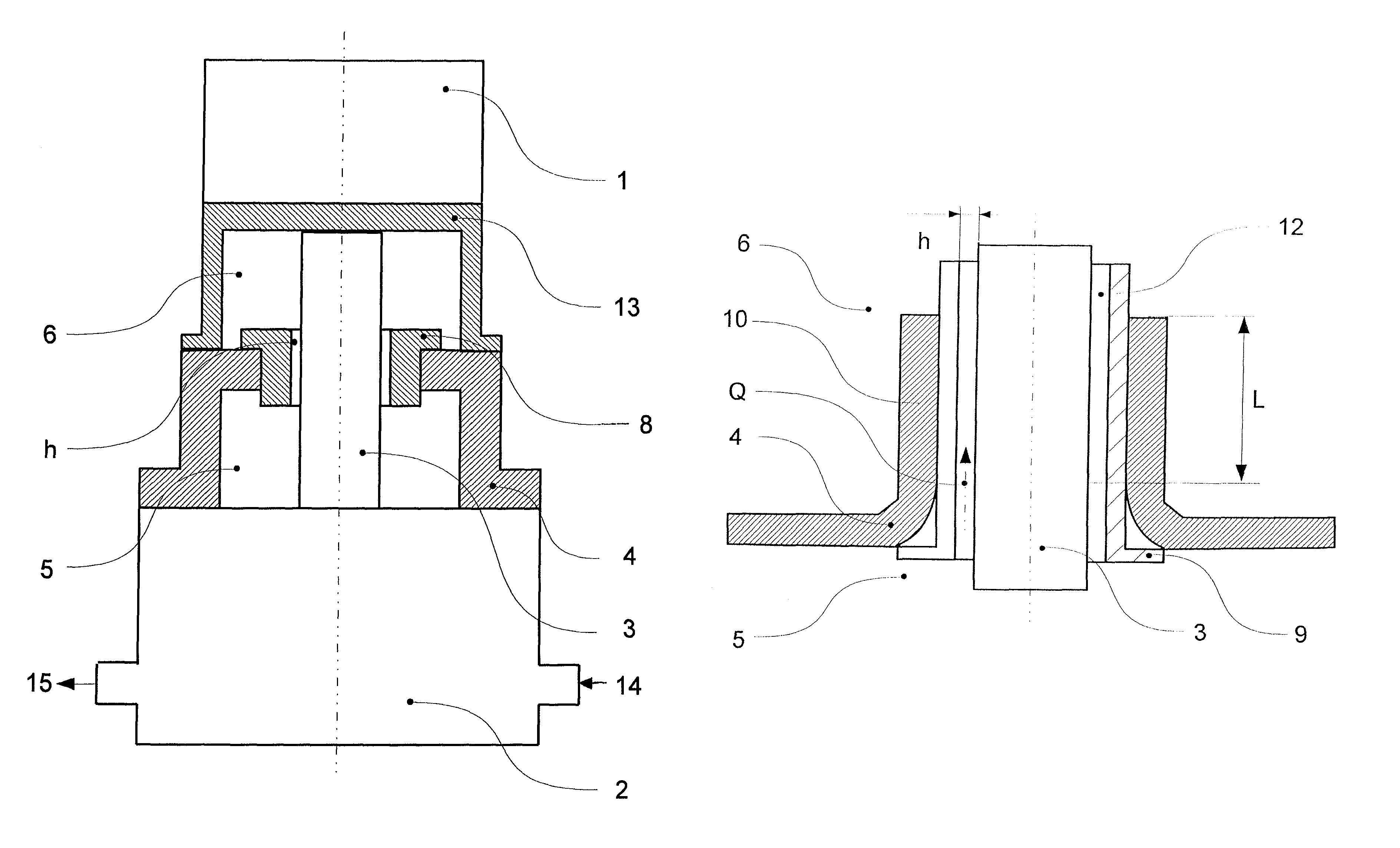
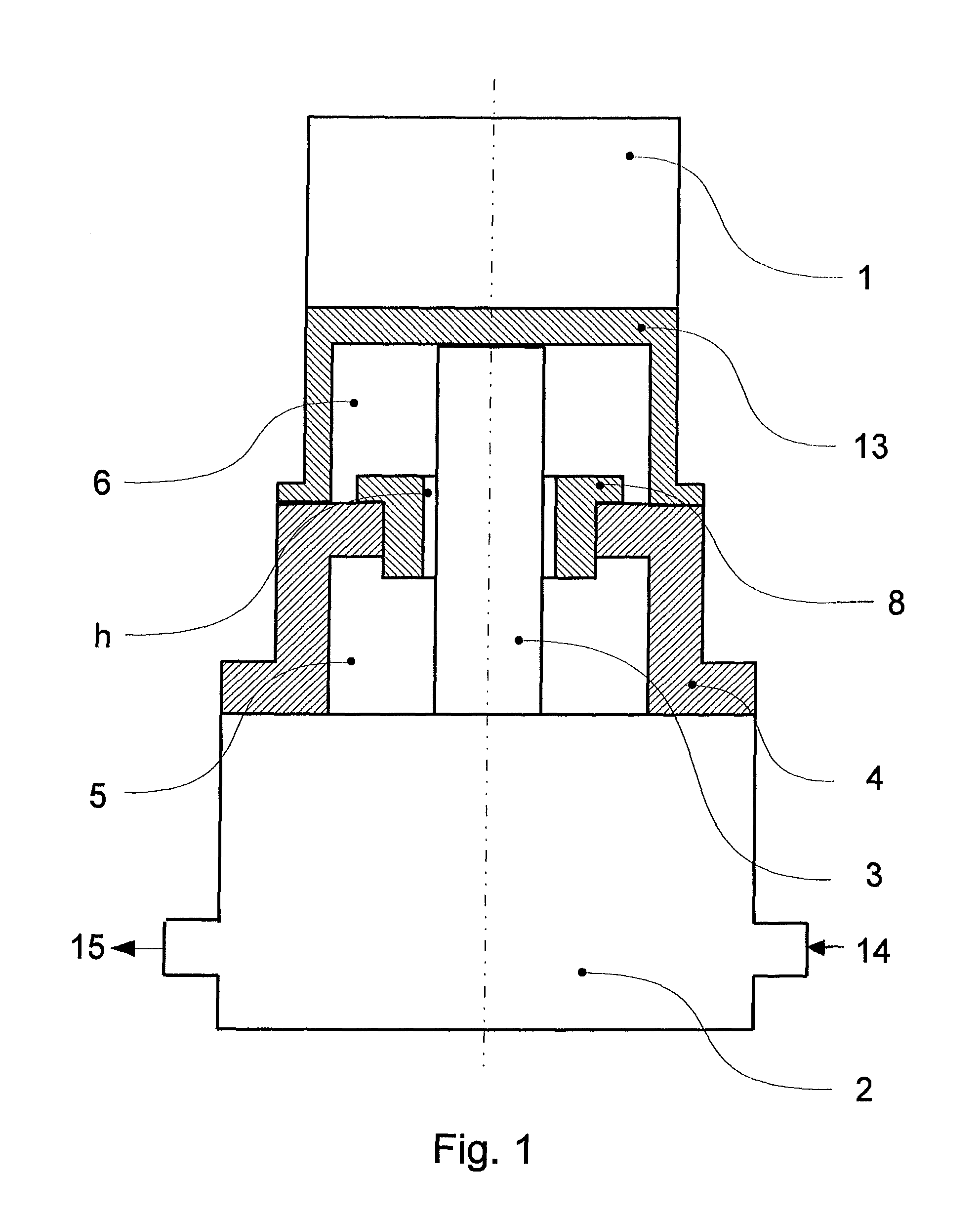
[0022]FIG. 1 illustrates a valve drive assembly applied on a valve body 2 in accordance with one embodiment of the present invention. Valve drive assembly includes a flange 4, an operating rod 3 and an annular element. Operating rod 3 is disposed through said flange. Fluid flows into valve body 2 from supply opening 14 and flows out of drain opening 15

[0023]A valve flap (not shown) disposed on operating rod 3 is arranged inside the valve body 2 as a means of driving, for example purely rotatory or by means of a linear movement or jointly by means of both types of movement. The f...


PUM


Abstract

The invention concerns an valve drive assembly for a valve unit for regulating a flow of fluid with a lead-through of an operating rod (3) through a flange (4), particularly the arrangement of operating rod (3) to the flange (4) for adjusting a defined flow of fluid. The assembly comprises a flange (4), and operating rod (3) and an annular element. The operating rod (3) is disposed through said flange, and annular element is disposed between flange (4) and operating rod (3) defining an annular gap (12) between the annular element and the operating rod. An effective length of the annular gap (12) exceeds a thickness of the flange (4). This invention leads to considerable cost savings, as the component parts can now be produced more simply using manufacturing processes known from mass production, such as deep-drawing or even stamping.

Description

CROSS REFERENCE TO RELATED APPLICATION(S)[0001]This application claims the benefit of German Patent Application Serial No. 102012108379.7 having a filing date of Sep. 7, 2012. The entire content of the aforementioned is hereby incorporated by reference for all purposes.FIELD OF THE INVENTION[0002]The invention relates to an actuator for a valve unit to regulate a flow of fluid from a modulation valve.BACKGROUND OF THE INVENTION[0003]In principle, a valve unit for regulating a flow of fluid comprises a valve body which restricts and controls fluid flows through its inside by means of a modulation-sealing system. Thus the fluid flows into an inlet opening of one side of the valve body and flows out through an outlet opening on the opposite side. To operate such a valve body, an actuator is connected upon an interposed flange, producing an intermediate chamber facing the valve between the actuator and the valve body. By means of a lead-through in the flange, the valve is operated by an...

Claims


Application Information

Patent Timeline
Patent Type & Authority Patents(United States)
IPC IPC(8): F16K41/00F16K31/44F16K41/04F16K41/08F16K5/06
CPCF16K31/44F16K41/003F16K41/04F16K41/08F16K5/0694F16K27/08
Inventor GASSMANN, JOERGMUELLER, THOMASFRAULOB, SEBASTIAN
Owner JOHNSON ELECTRIC SA
Why Eureka
Try Eureka