Methods and systems for creating and interacting with three dimensional virtual models

a three-dimensional virtual model and system technology, applied in the field of computer-based methods and systems, can solve problems such as significant patient discomfort, and achieve the effect of quick and easy

Active Publication Date: 2016-03-29
ALIGN TECH
View PDF12 Cites 87 Cited by
  • Summary
  • Abstract
  • Description
  • Claims
  • Application Information

AI Technical Summary

Benefits of technology

[0179]A feature of at least this embodiment is that it allows the dental practitioner to modify a dental structure (such as for example a dental preparation or a missing or modified tooth) in a quick and easy manner with a minimum of scanning after the initial virtual scan.

Problems solved by technology

However, it is often the case that when scanning the intra oral cavity to obtain 3D data of the preparation and finish line, on which the virtual model is based, part of the finish line, and possibly also the shoulder and other parts of the preparation, may be obscured by soft tissues such as the gum that, no longer being supported by the dental surfaces that have been removed, deform to cover at least a part of the finish line on the prepared dental site.
Similar issues may arise when scanning the intra oral cavity to obtain 3D data of the position and orientation of a dental implant in relation to the surrounding portions of the intra-oral cavity, and in addition the corresponding impression abutment (also referred to herein as a scanning body) may partially obscure part of the intra-oral cavity.
Similarly, there are other situations in which a virtual model of a physical item, obtained from scanning the physical item, is partially obscured or incomplete, or in which part of the physical item needs to be subsequently modified after obtaining the virtual model.
Such situations would conventionally require a rescanning of the entire physical item, and this may involve significant additional time, inconvenience and, where the physical item is a part of the body of a patient (such as for example the intra oral cavity), this may also involve significant patient discomfort.

Method used


Image

  • Methods and systems for creating and interacting with three dimensional virtual models
  • Methods and systems for creating and interacting with three dimensional virtual models
  • Methods and systems for creating and interacting with three dimensional virtual models

Examples


first embodiment

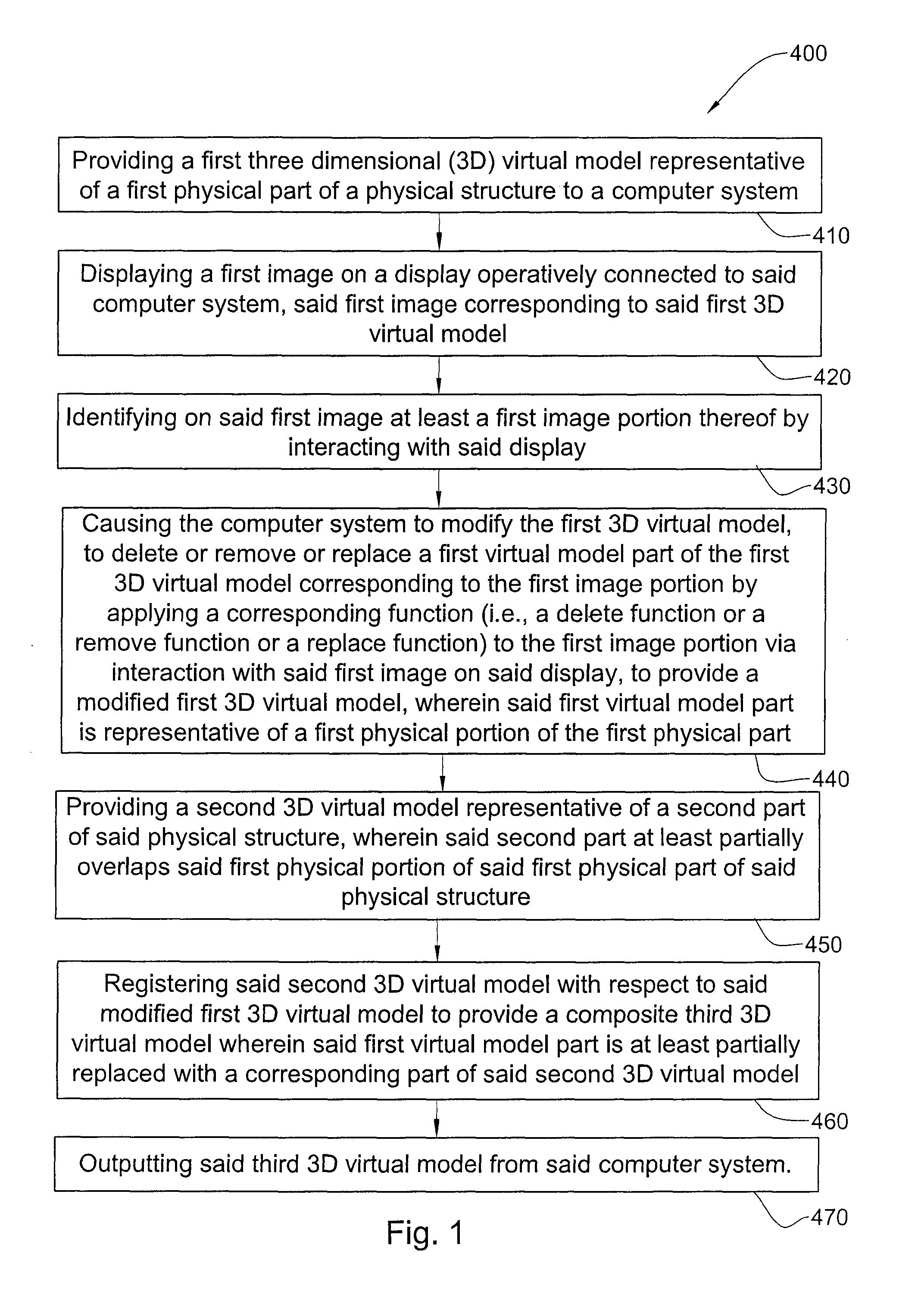
[0191]A computer-based method, particularly useful for creating, manipulating and refining a virtual dental model, according to the invention and designated with reference numeral 400 is illustrated in FIG. 1.

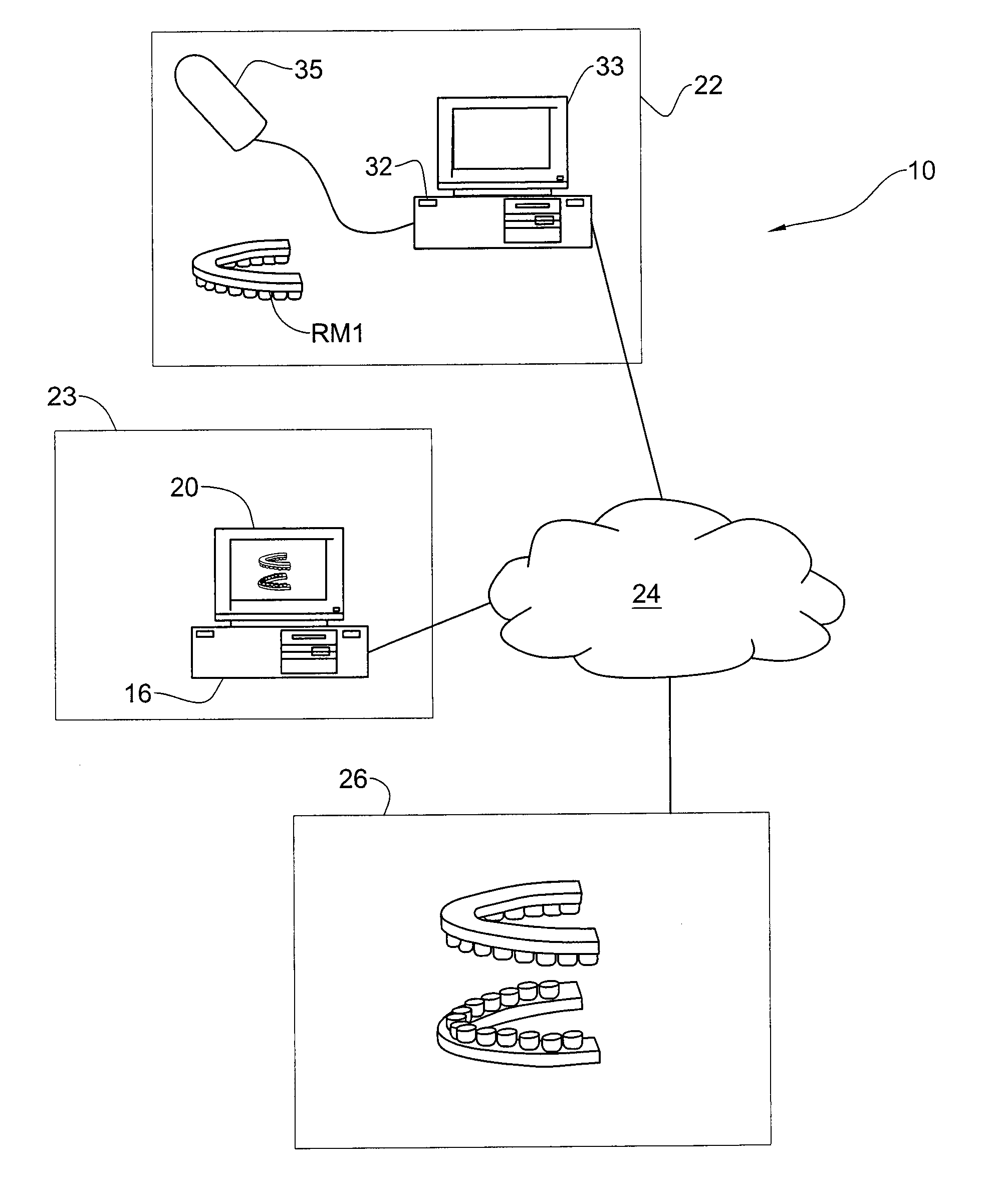
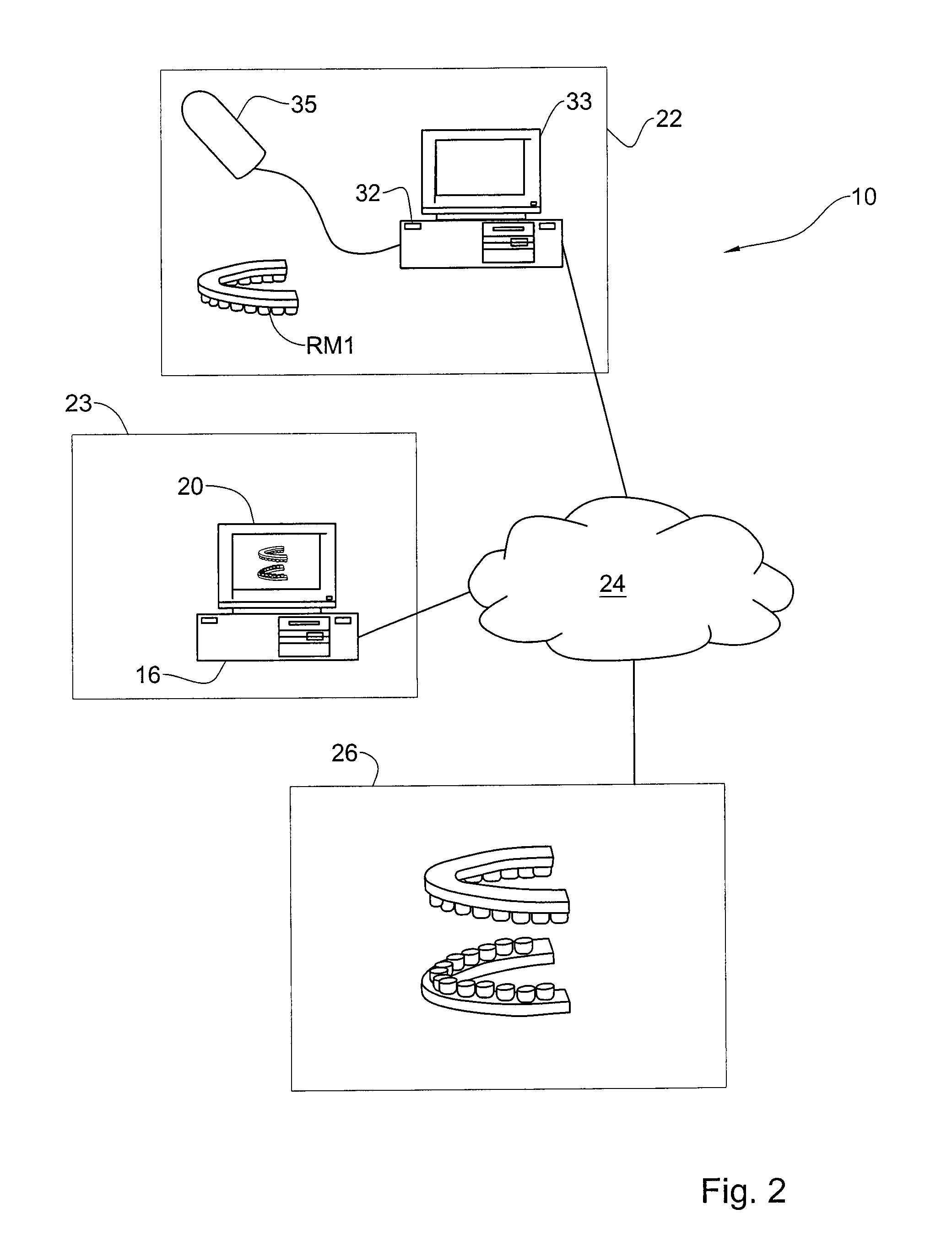
[0192]In step 410 carried out by the method 400, an accurate 3D representation, i.e., a first 3D virtual model of a physical structure, in this example the intraoral cavity, is obtained. This first 3D virtual model is generally designated with the numeral VM1 in the accompanying figures. As used herein, and as already discussed, the intra oral cavity can include one or more real teeth and / or one or more prosthetic teeth and / or part of one or more real teeth of one jaw or of both jaws of a patient, and / or can also include all the real teeth and / or prosthetic teeth in one or both jaws, and / or adjacent gingiva and other adjacent objects of the patient, and / or can include a physical model or other physical representation of one or more or all the real teeth, and / or one or more or a...

second embodiment

[0250]Method 400′ may be applied in a corresponding manner to the second embodiment, mutatis mutandis.

[0251]It is readily evident that by carrying out this embodiment of the invention, it allows obtaining a virtual model of the intra oral cavity including such an artifact, wherein even the parts of the dental surfaces obscured by the artifact can be fully defined with respect thereto, even when originally obscured by the artifact.

[0252]Referring to FIG. 8, a third embodiment of the invention has all the elements, features and steps of the first embodiment including steps 410 to 470 or alternative variations thereof, for example steps 410′ to 470′, mutatis mutandis, the main difference being that the physical part RM1 in the third embodiment is considered to be well defined in the first virtual model VM1, i.e., faithfully represents the surfaces of interest of the physical part RM1; however, a first physical portion of the physical part RM1 is not considered suitable for a dental pro...

third embodiment

[0263]Method 400′ may be applied in a corresponding manner to the third embodiment, mutatis mutandis.

[0264]It is also readily evident that by carrying out this embodiment of the invention, it allows the dental practitioner to modify a dental structure such as dental preparation in a quick and easy manner with a minimum of scanning after the initial virtual scan. i.e., without the need to rescan the whole physical part RM1 again each time.

[0265]It also readily evident that parts or all of the method steps according to each of the first, second and third embodiments and / or alternative variations thereof may be applied to one or more of the other embodiments as well.

[0266]It is also readily evident that the method (and corresponding system) according to each of the first, second and third embodiments and / or alternative variations thereof may further comprise a manufacturing step, in which a dental object may be manufactured based on the respective composite third 3D virtual model VM3 u...


PUM


Abstract

Systems and methods are provided for modifying a virtual model of a physical structure with additional 3D data obtained from the physical structure to provide a modified virtual model.

Description

CROSS-REFERENCE TO RELATED APPLICATIONS[0001]The present application is a U.S. National Phase Application under 35 U.S.C. §371 of International Application No. PCT / IL11 / 00574, filed Jul. 19, 2011, entitled “METHODS AND SYSTEMS FOR CREATING AND INTERACTING WITH THREE DIMENSIONAL VIRTUAL MODELS,” which claims priority to U.S. Provisional Patent Application No. 61 / 365,556, filed Jul. 19, 2010, entitled “METHOD FOR CREATING AND INTERACTING WITH THREE DIMENSIONAL VIRTUAL MODELS USEFUL FOR DENTAL PROCEDURES,” the entire contents of which are incorporated herein by reference.FIELD OF THE INVENTION[0002]This invention relates to computer based methods and systems, particularly to computer based methods and systems that are useful in dentistry and other fields, and that are particularly useful in prosthodontics and / or orthodontics in particular.BACKGROUND OF THE INVENTION[0003]There are many procedures associated with the intra oral cavity in which a precise three-dimensional virtual represe...

Claims


Application Information

Patent Timeline
Patent Type & Authority Patents(United States)
IPC IPC(8): G06T19/00G06T19/20A61C13/00A61C7/00
CPCG06T19/00A61C7/002A61C13/0004G06T19/20G06T2210/41G06T2219/2021B33Y80/00A61C5/77G16H20/40G06F30/00G06F30/20A61B1/0004G06T7/0012G06T2200/04G06T2207/30036G06T2219/2004A61B1/00172A61B5/0062A61B5/0088A61B5/4547A61C9/0053A61C19/04
Inventor KOPELMAN, AVI
Owner ALIGN TECH
Why Eureka
Try Eureka