Phase difference signaling in MIMO mode uplink

a technology of phase difference and uplink communication, applied in the field of wireless communication, can solve the problems of burden on the ue, difficult for the ue to do, and loosen the effect of transmission phase adjustmen

Active Publication Date: 2016-03-29
QUALCOMM INC
View PDF9 Cites 1 Cited by
  • Summary
  • Abstract
  • Description
  • Claims
  • Application Information

AI Technical Summary

Problems solved by technology

When the UE is not able to maintain relative transmit phase continuity, however, the transmit phase adjustment looses effectiveness.
It is often burdensome to require that a UE maintain relative transmit phase at a constant or near constant value.
Several factors make it difficult for a UE to do so.
Improper transmitter calibration may allow one or more of the transmitters to change in phase over time.
As a result, UEs often lack circuitry and / or software necessary to properly initialize or keep track of the phase of each transmitter.
However, the individual transmit chains are usually not identical due to design differences or part to part variations, therefore the relative transmit phase continuity will not be maintained.
This approach is undesirable because it is both computationally burdensome and expensive.

Method used


Image

  • Phase difference signaling in MIMO mode uplink
  • Phase difference signaling in MIMO mode uplink
  • Phase difference signaling in MIMO mode uplink

Examples


Embodiment Construction

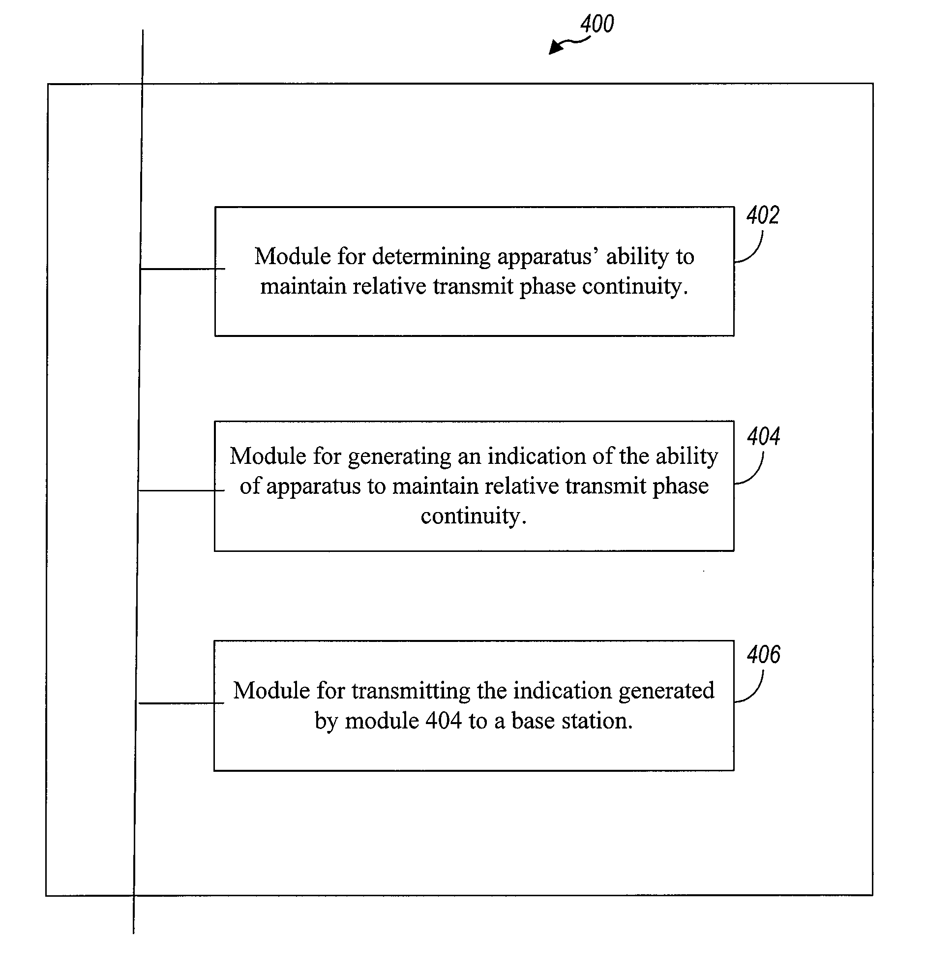
[0025]As will be better appreciated from the discussion which follows, representative aspects of the present disclosure are directed to an uplink signaling scheme that allows a UE to avoid the expense and burden of maintaining relative transmit phase continuity between its transmitters while still providing satisfactory wireless communication links. In implementing such uplink transmission schemes according to embodiments, a UE transmits to a base station an indication of its ability to maintain relative transmit phase continuity with respect to a plurality of transmit chains thereof (e.g., a first and a second UE transmitter signal path). The base station uses the information regarding the UE's ability to maintain relative transmit phase continuity in adopting an uplink transmission format used with respect to the UE. For example, the base station may adopt an uplink transmission format biased toward selecting precoders that are not sensitive to phase difference, the base station m...


PUM


Abstract

An uplink signaling method is described where the UE transmits an indication of its ability to maintain relative transmit phase continuity with respect to a plurality of transmit chains thereof in place of being required to actually maintain the phase difference between its transmitters. The signaling method utilizes straightforward signaling with very little overhead, because the indication may be provided by setting the value of a bit in an uplink transmission. In response, a base station adopts an uplink transmission format for communications by the UE based, at least in part, upon the received indication.

Description

TECHNICAL FIELD[0001]The present disclosure relates generally to wireless communications and more specifically to techniques for uplink communication in a multi-input multi-output (MIMO) wireless communication system.BACKGROUND OF THE INVENTION[0002]Wireless communication systems are widely deployed to provide various communication content such as voice, video, packet data, messaging, broadcast, etc. These wireless systems may be multiple-access systems capable of supporting multiple users by sharing the available system resources. Examples of such multiple-access systems include Code Division Multiple Access (CDMA) systems, Time Division Multiple Access (TDMA) systems, Frequency Division Multiple Access (FDMA) systems, Orthogonal FDMA (OFDMA) systems, and Single-Carrier FDMA (SC-FDMA) systems.[0003]A wireless communication system may include a number of base stations that can support communication for a number of user equipments (UEs). A base station may include multiple transmit a...

Claims


Application Information

Patent Timeline
Patent Type & Authority Patents(United States)
IPC IPC(8): H04B7/04H04W72/04H04B17/12H04L27/26
CPCH04B7/0404H04B17/12H04L27/2647H04W72/048H04W72/51
Inventor GAAL, PETER
Owner QUALCOMM INC
Why Eureka
Try Eureka